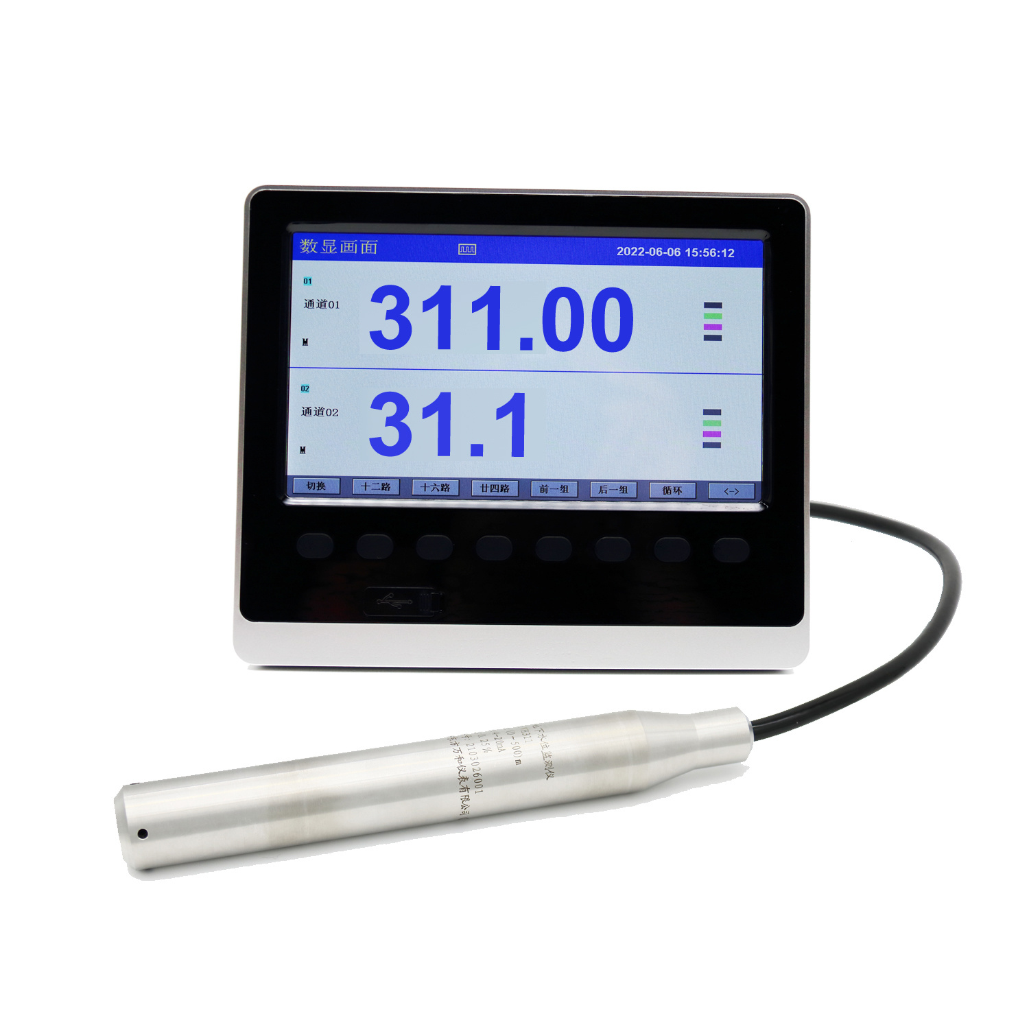
Groundwater level measurement in multiple deep wells in the Gezhouba underground space
Case Description
I. Specific Requirements
User: Gezhouba Nanjing Underground Space
Requirements: Well depth of 100 meters. The user needs real-time monitoring of the water level in 16 deep wells, with real-time digital display of the liquid level at the wellhead. Data needs to be recorded every minute, in real-time, and exportable via USB drive in a table format.
II. Requirements Analysis
1. Measurement Object
Real-time monitoring of the water level in 16 deep wells (100 meters deep) with recording functionality; water level monitoring of tunnel fire and life water pools
2. Real-time Display
Real-time monitoring of the actual water level in each well is required on-site, with a four-digit display.
3. Data Recording
16 channels integrated using a water level automatic recorder to collect, display, process, store, and print 16 channels of water level data in real-time.
III. Equipment Composition
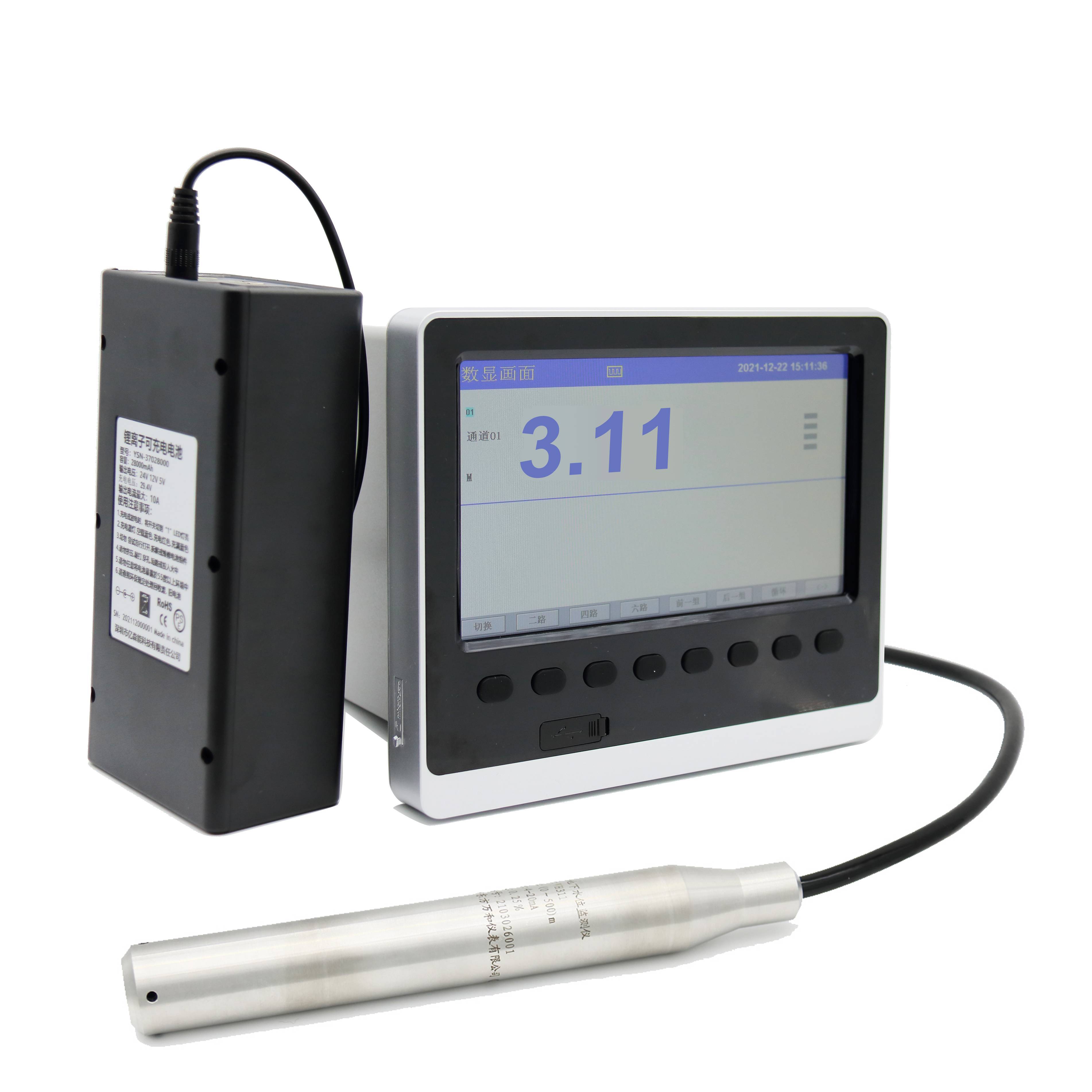
The deep well water level measurement and recording system mainly includes:
1. Water level data acquisition and transmission equipment: WH311 lightning protection type deep well liquid level transmitter.
2. Data display equipment:
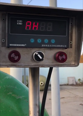
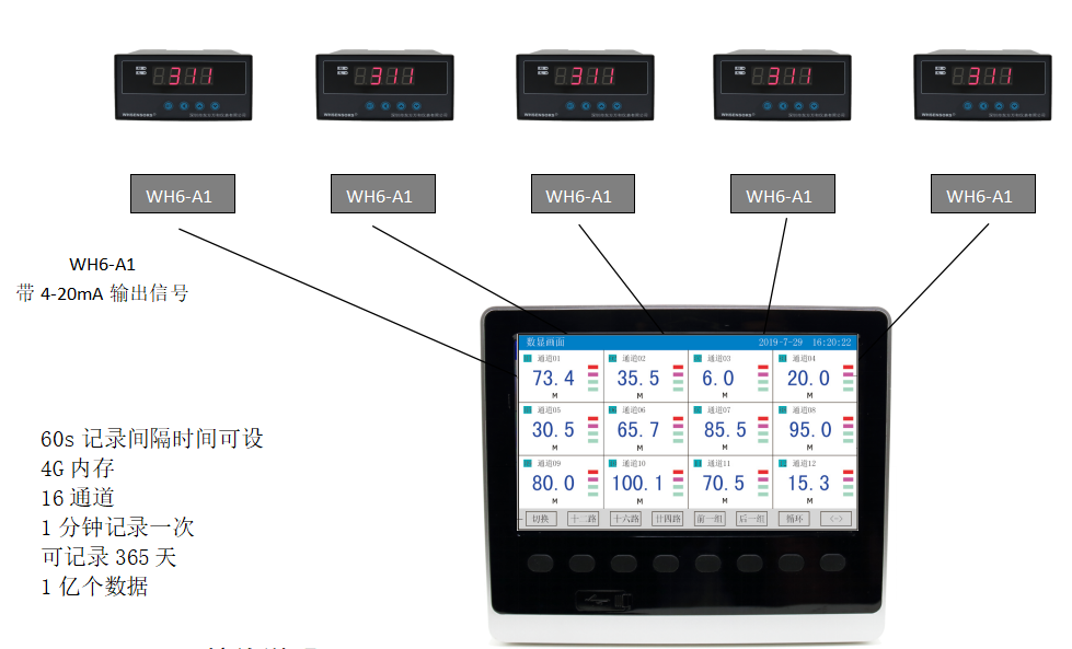
WH6-A1 deep well water level measurement display, with a 4-20MA output module for the display recorder.
3. Data storage equipment:
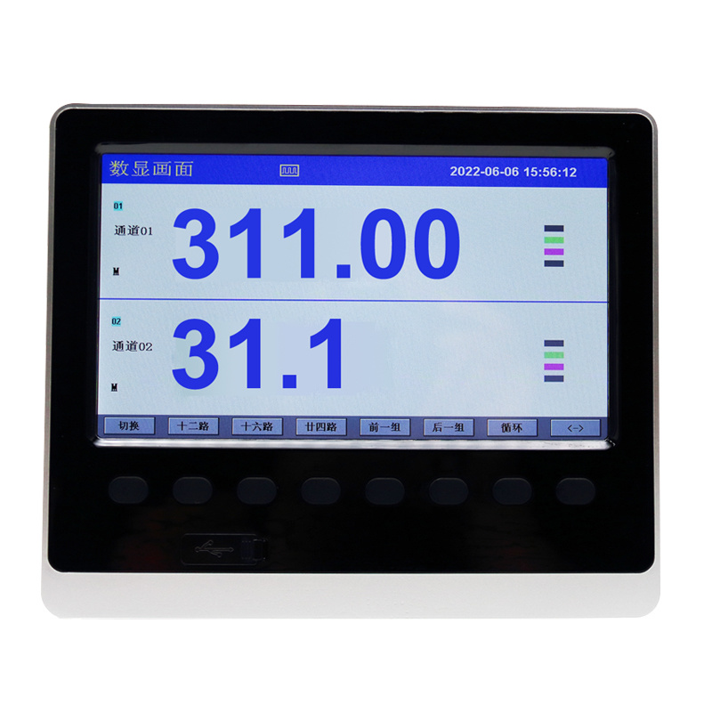
WH6-16T display recorder, 16 or 18 channels are optional.
If no pre-allocation is available, select 16 channels.
Memory: 4G memory is selected, and recording can be set to once per minute.
Data recording time: 16 channels record data once per minute, capable of recording 365 days of data.
IV. Scheme Design Diagram
V. Wiring Instructions

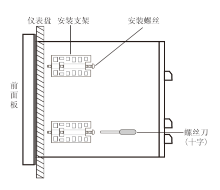
● Instrument Installation
(1) Installation Method
A. Insert the instrument from the front of the instrument panel
B. Install using the instrument's mounting bracket, as shown in the figure on the right
▲ Secure with four mounting brackets on both sides of the instrument
(2) Installation diagram shown below
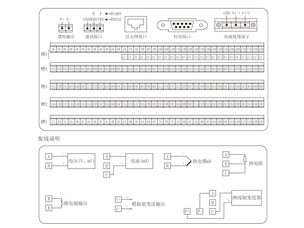
1. Place the WH311 level probe directly at the bottom of the 100-meter deep well. It can be lowered with the deep well pump. Protect the steel wire cable during the lowering process (if the cable is damaged, there will be no output signal).
2. Connect the on-site digital display from the WH6-A1's terminal 4 and terminal 5 using a 2*1.5 square shielded cable to the control room display recorder. Then, connect terminal 4 of display 1 to 1C and terminal 5 to 1A according to the number.
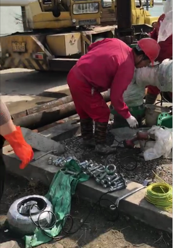
On-site Pictures
Amount of reading:
2024-12-12
Previous Page
Previous Page
Leave us a message


