


Pool 1

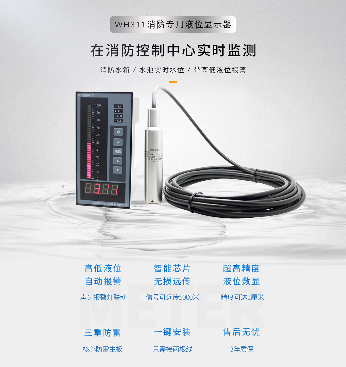
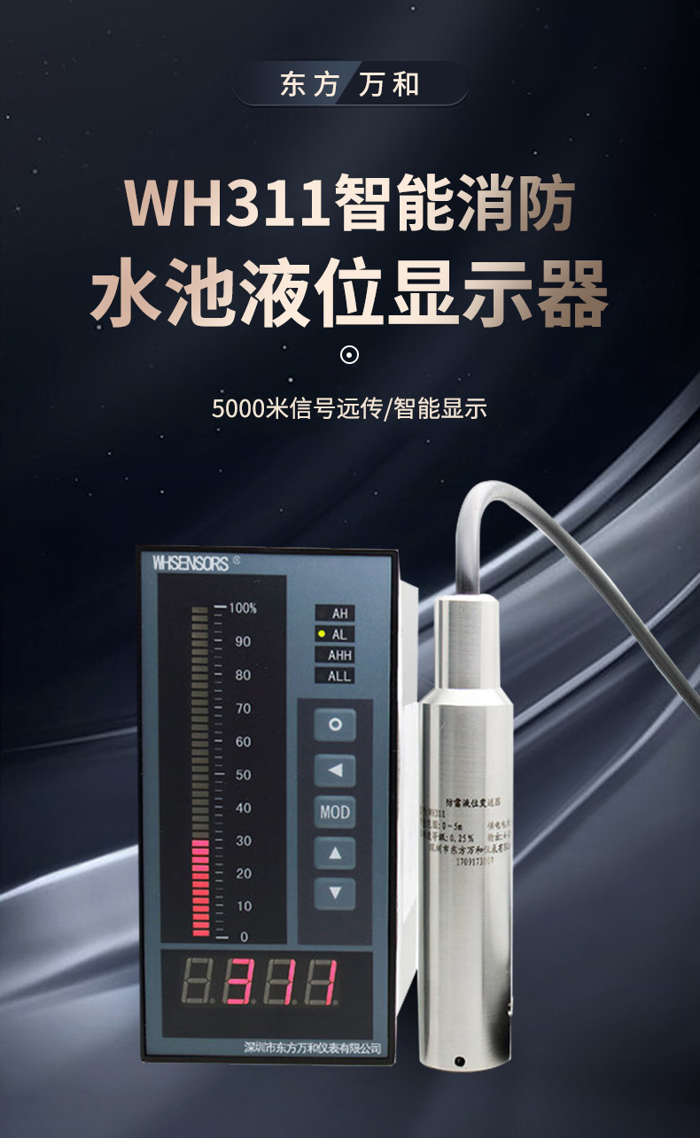
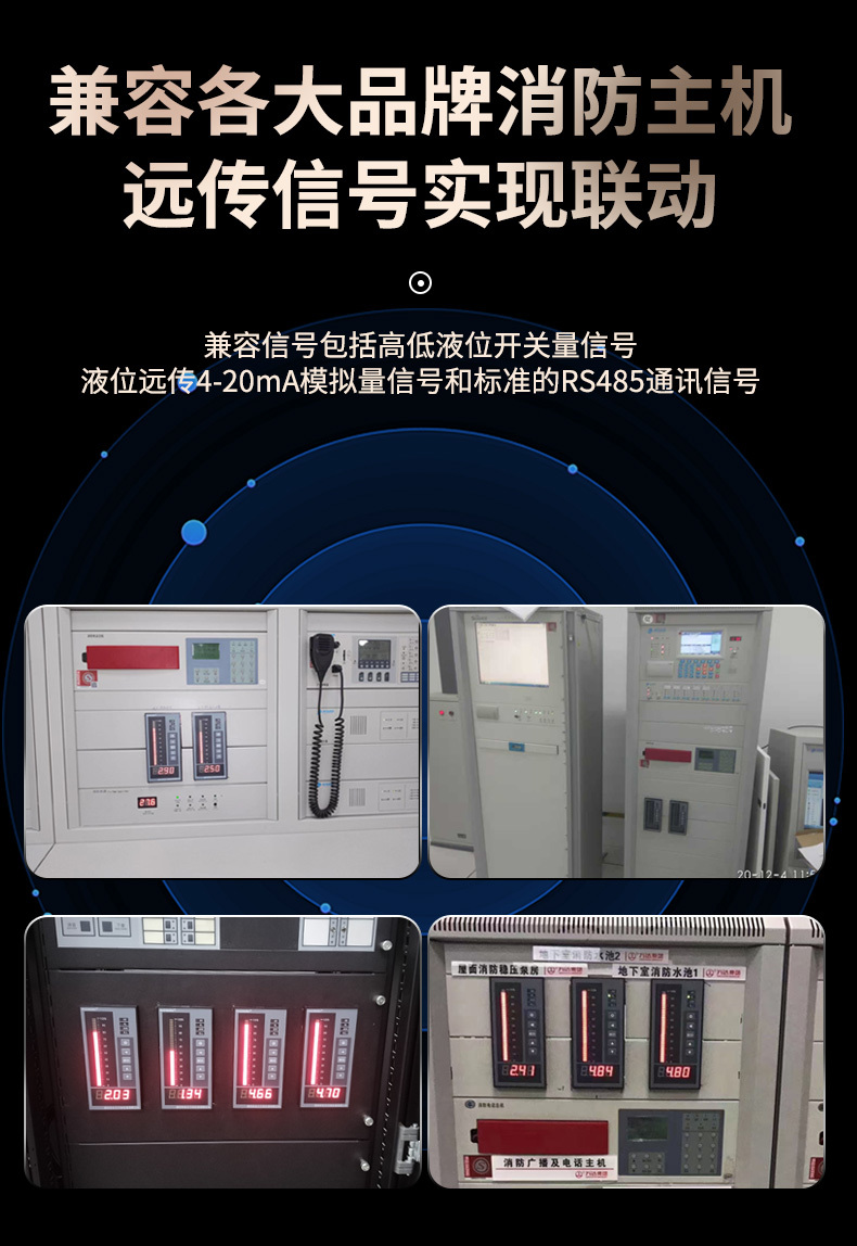
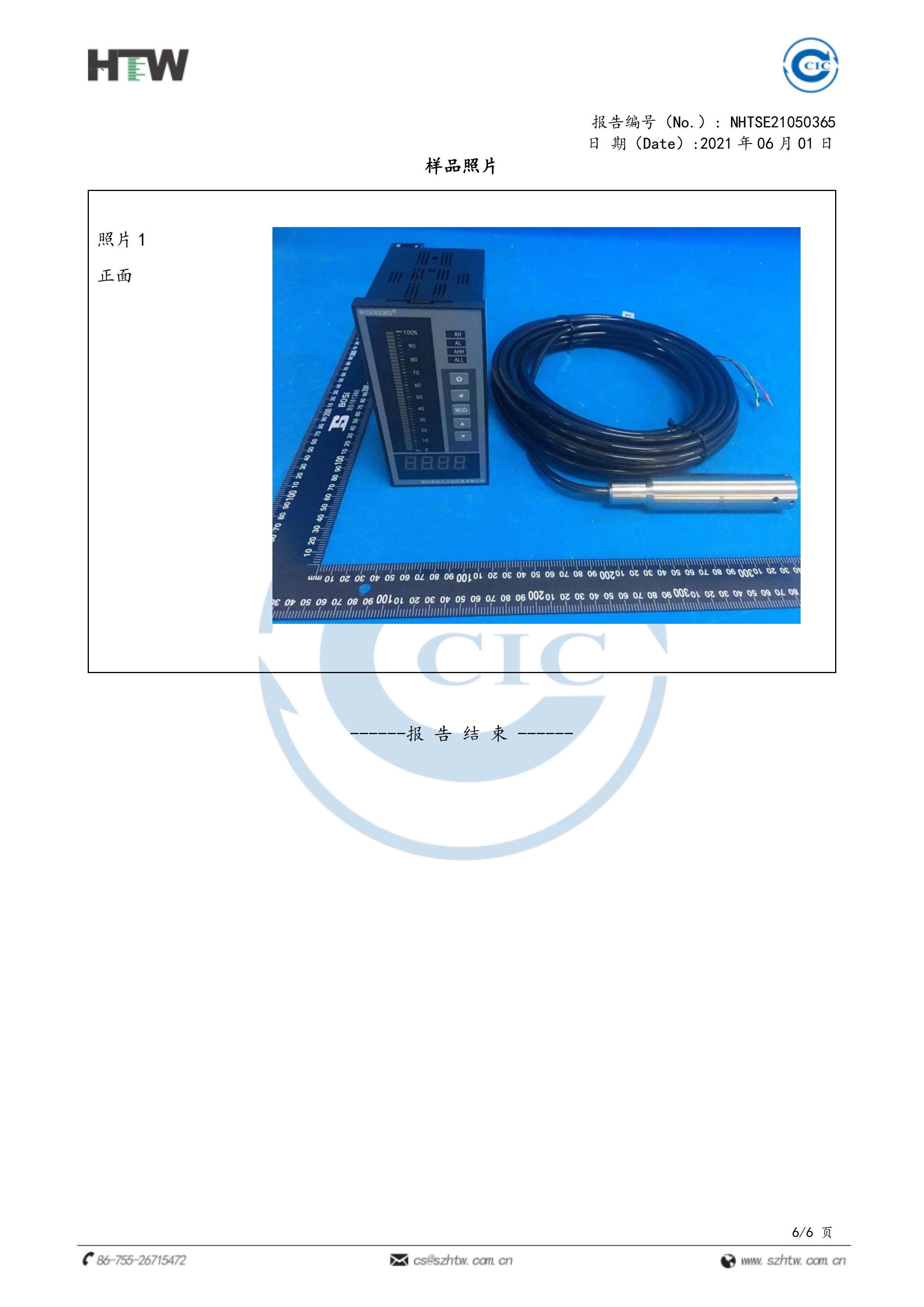
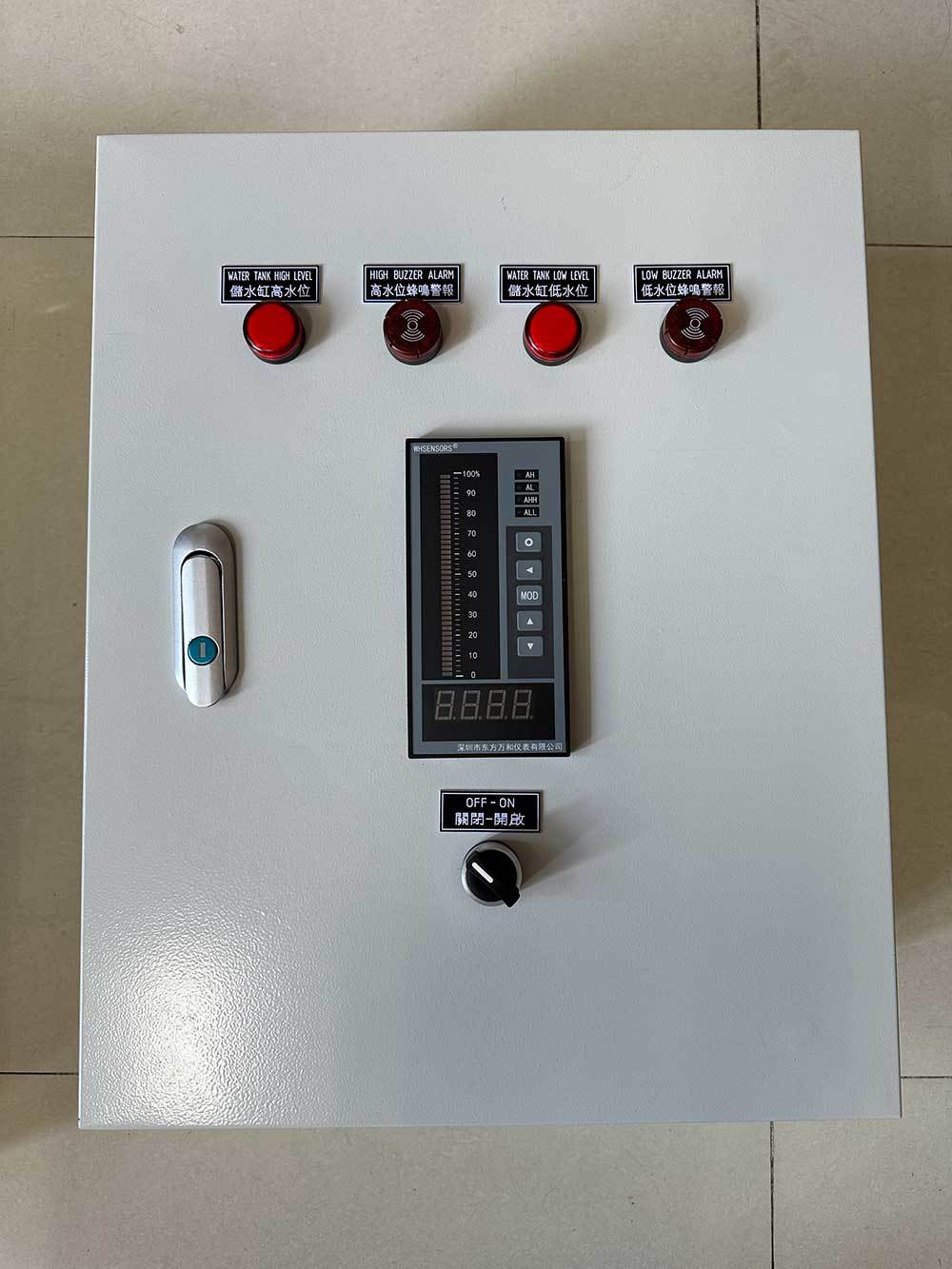
Water tank level display devices
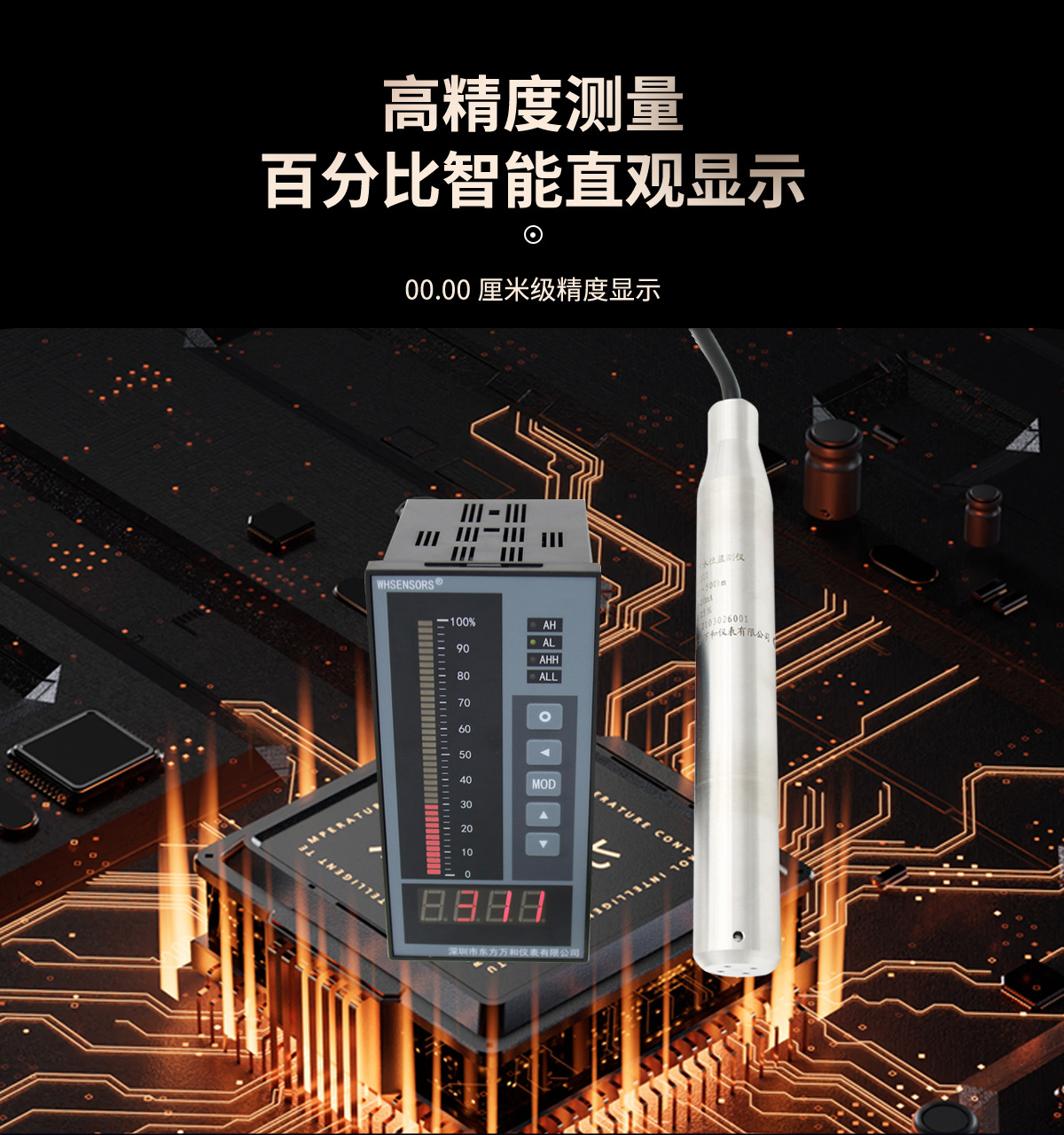
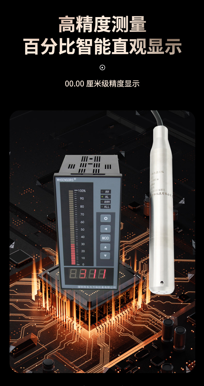
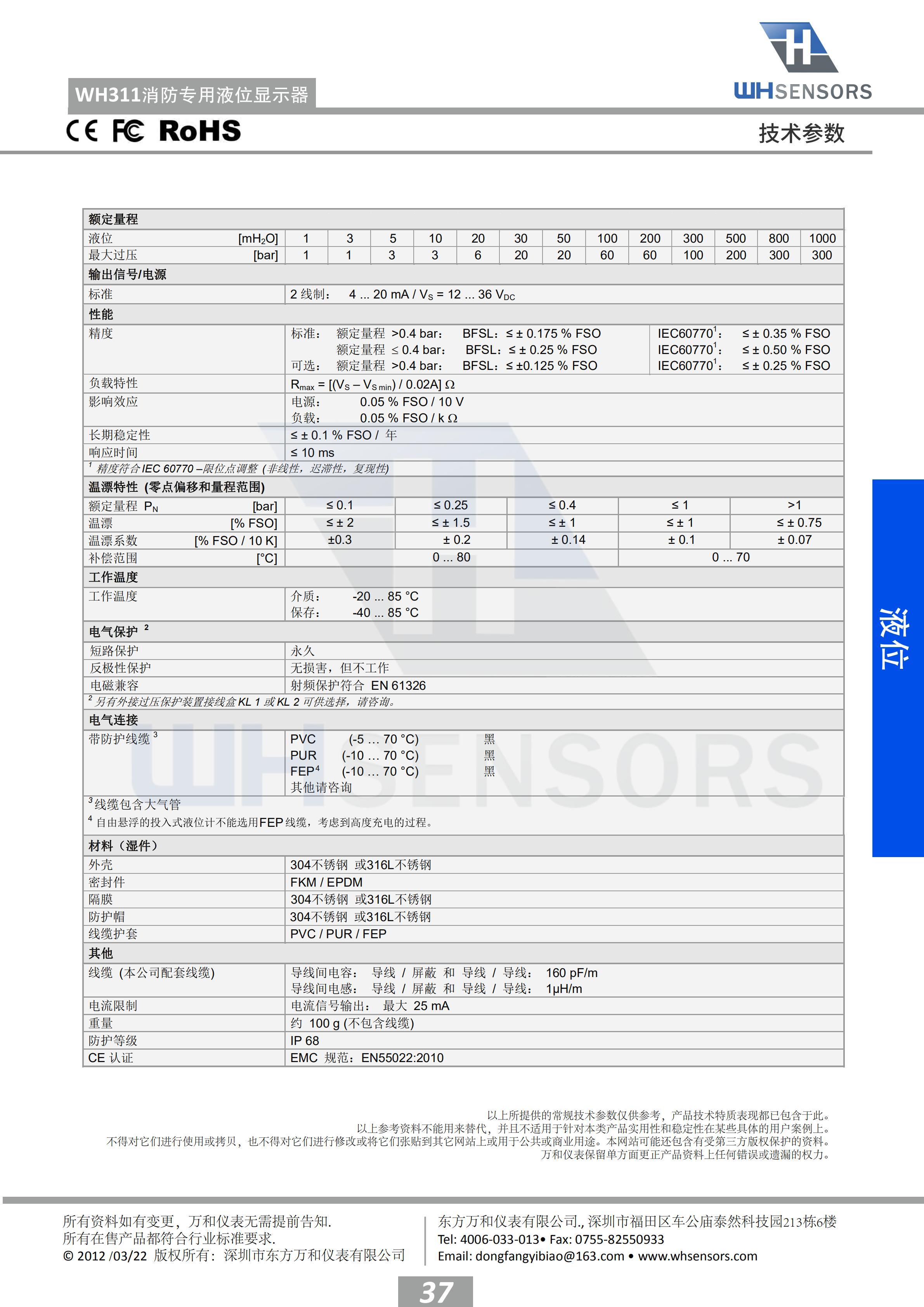
Measuring range: 0-100.00mH2O
Output signal: 4-20mA
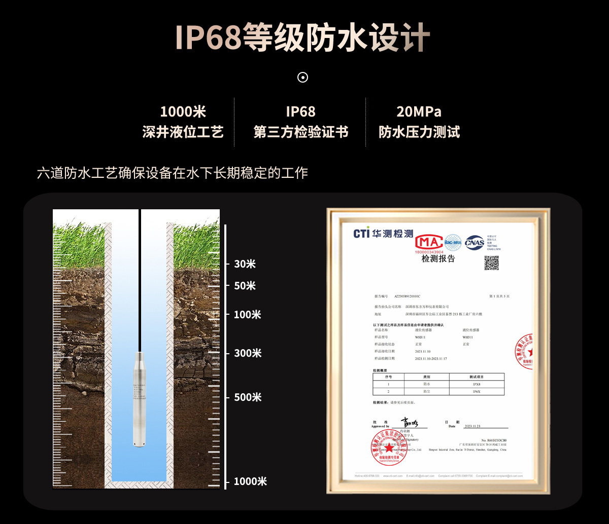
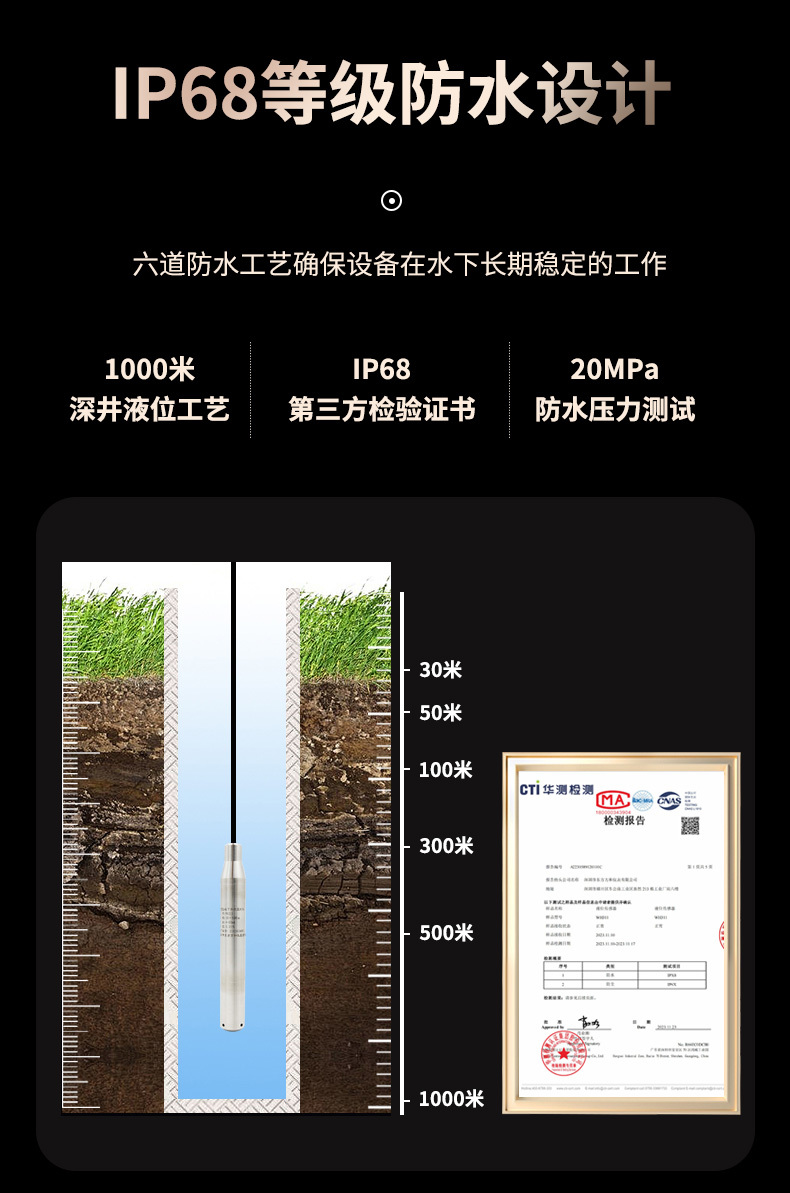
Protection level: IP68
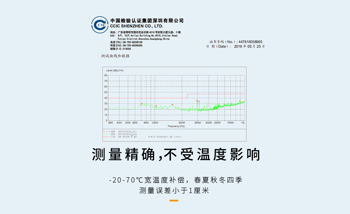
Temperature compensation: -20-85℃
Accuracy: 0.1%FS, 0.25%FS, 0.5%FS
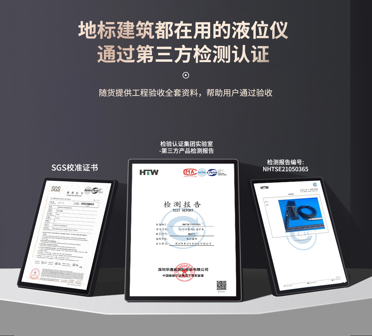
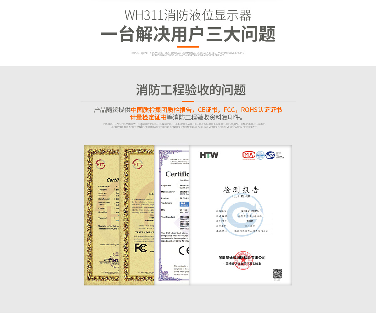
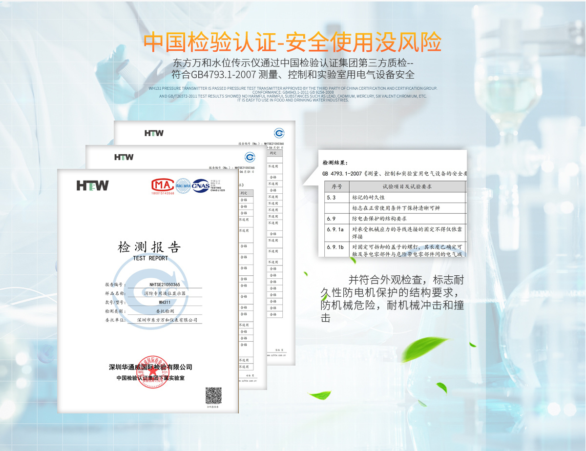
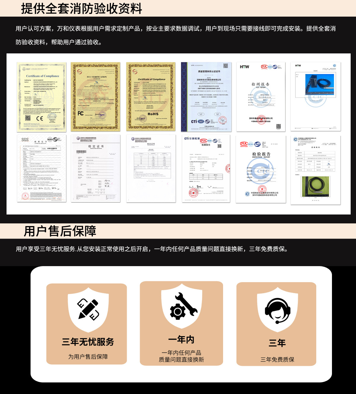
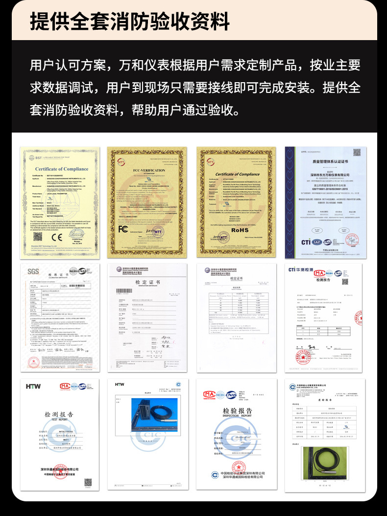
Certification Information:
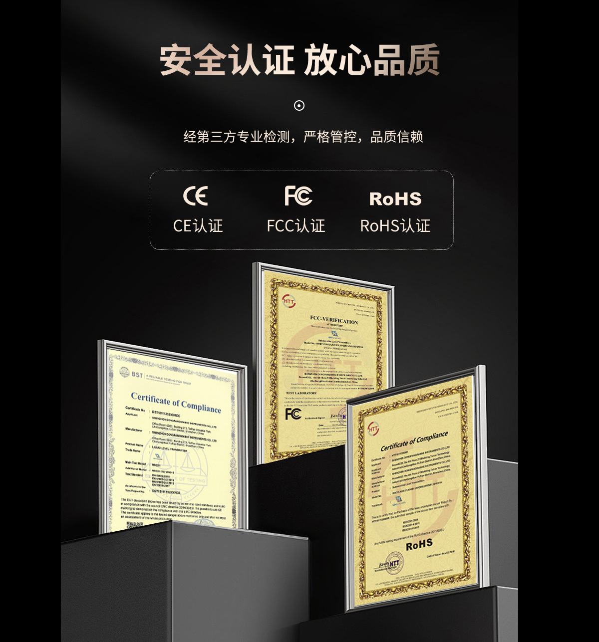
1 CE FCC RoHS
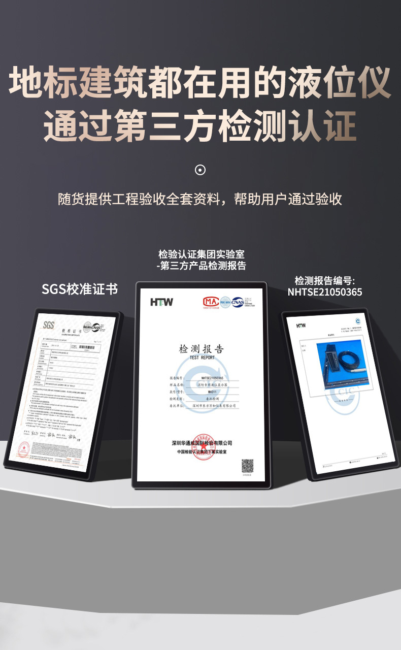
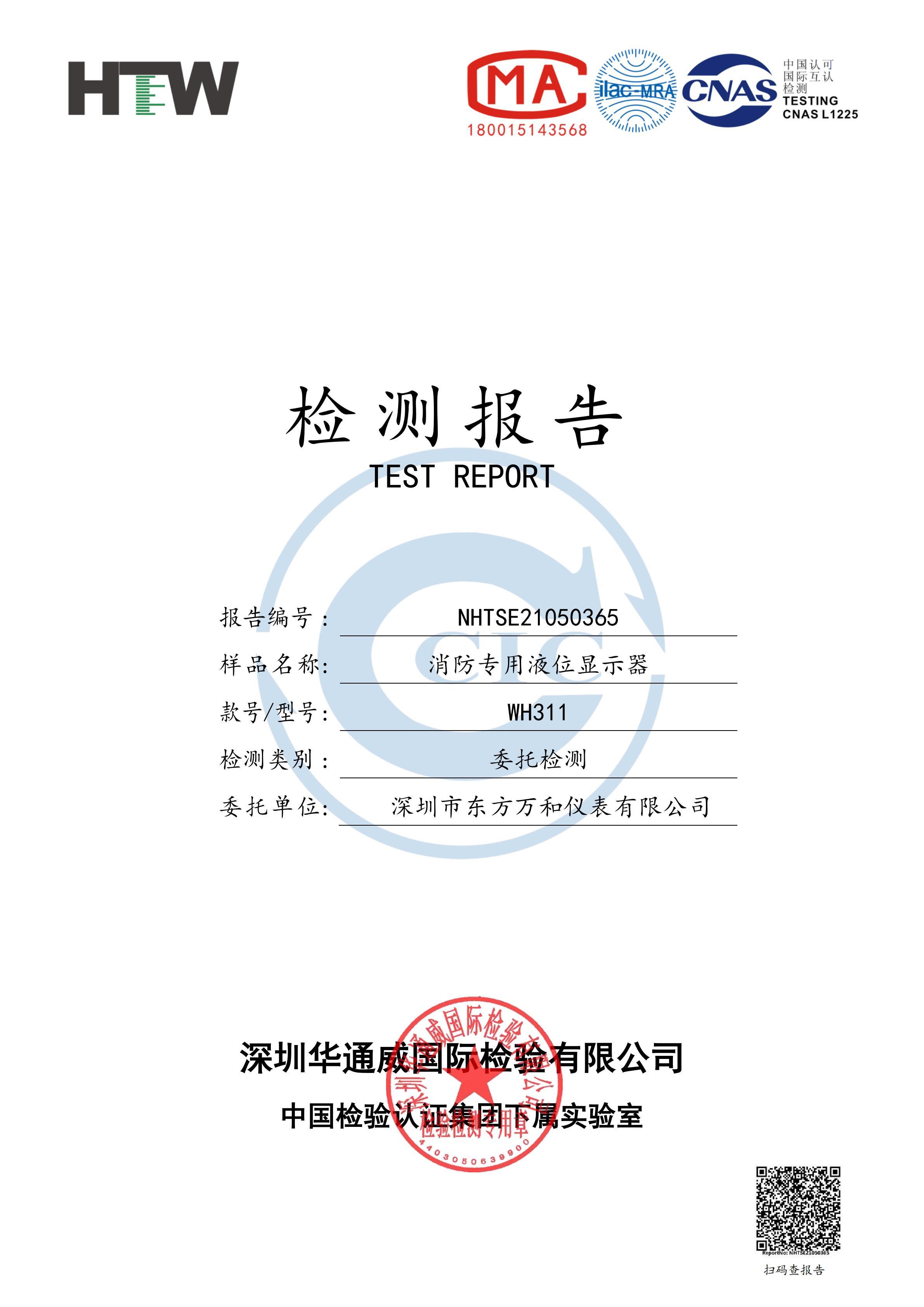
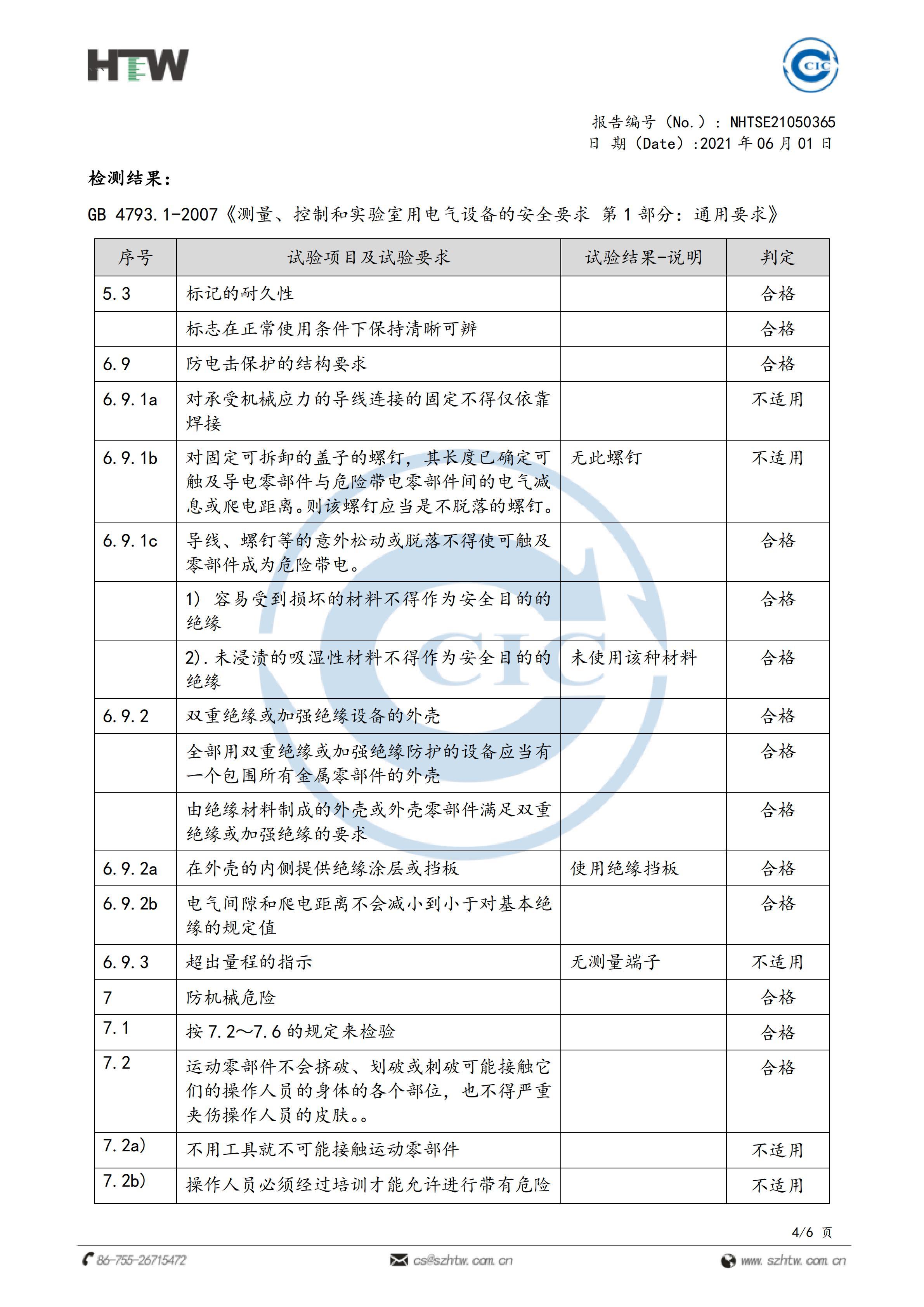
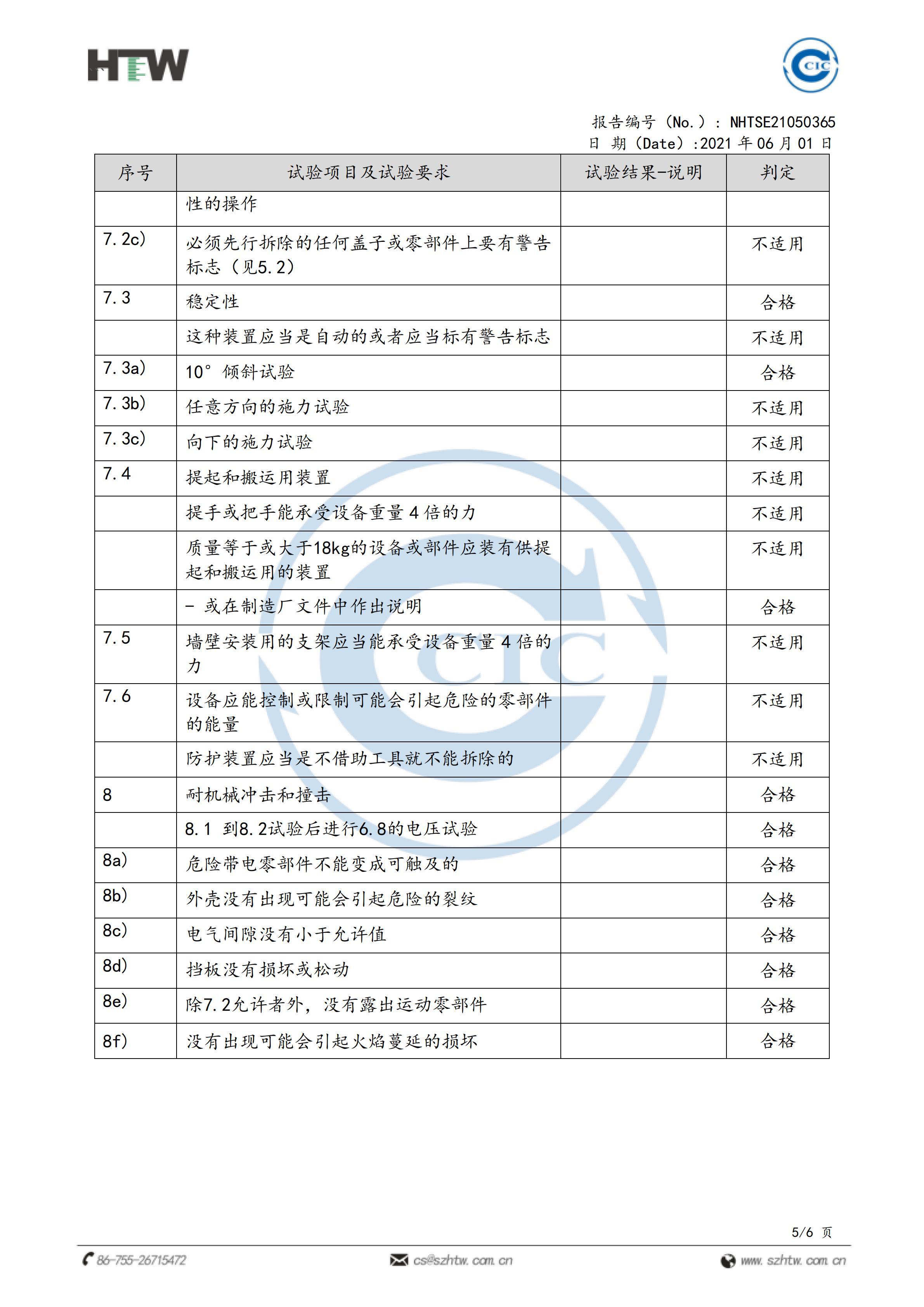
2 Fire safety third-party inspection report
3 This product has been tested by SGS and the error is 0.009mA
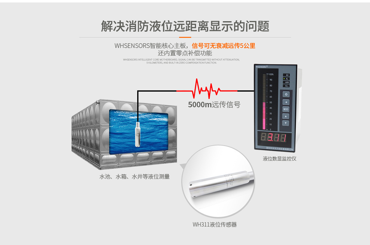
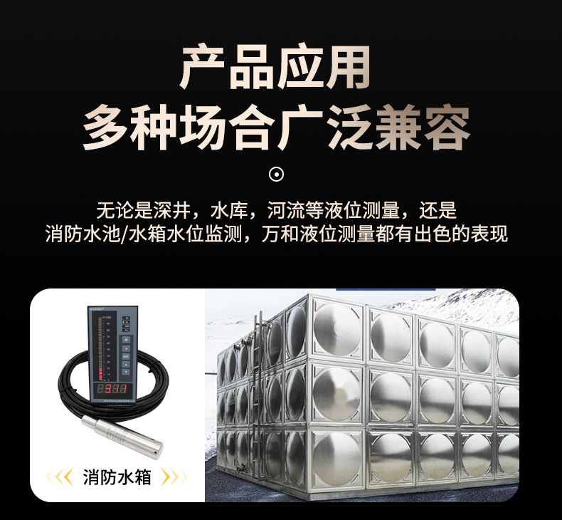
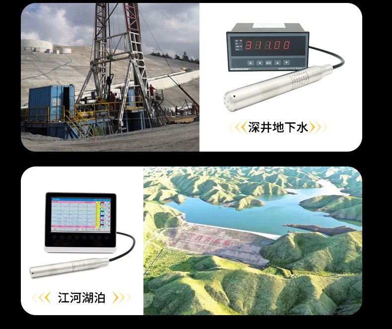
Suitable for remote transmission of water level in fire water tanks and pools
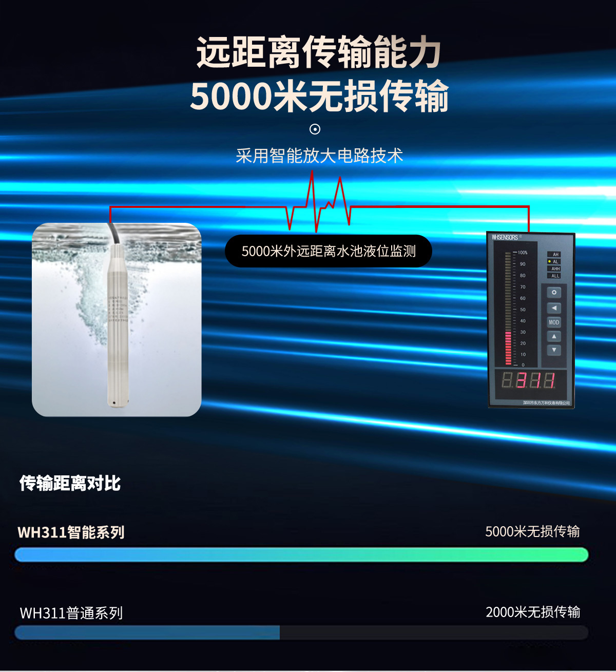
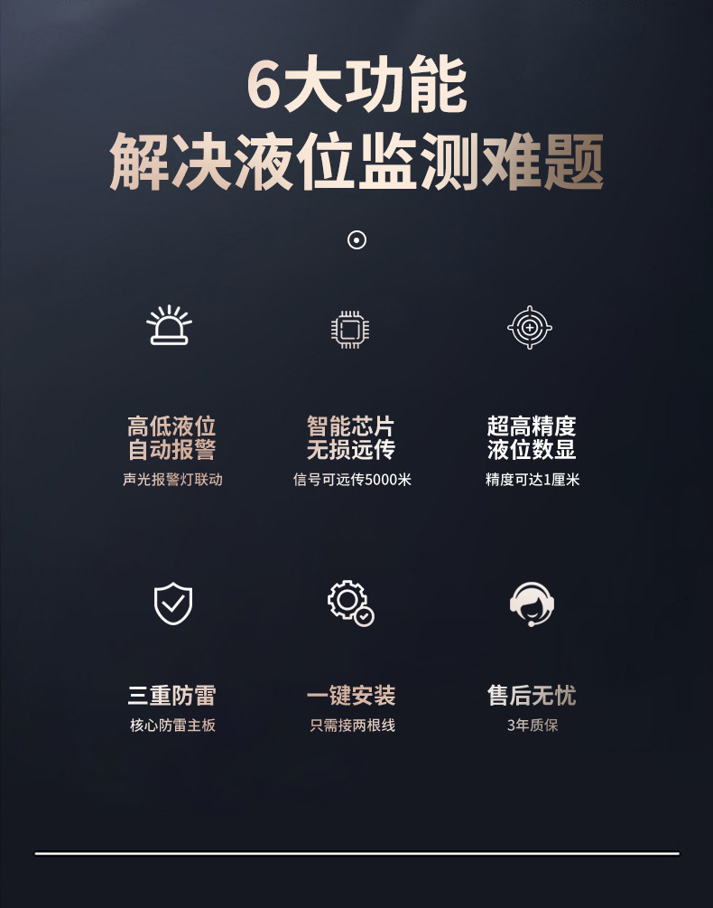
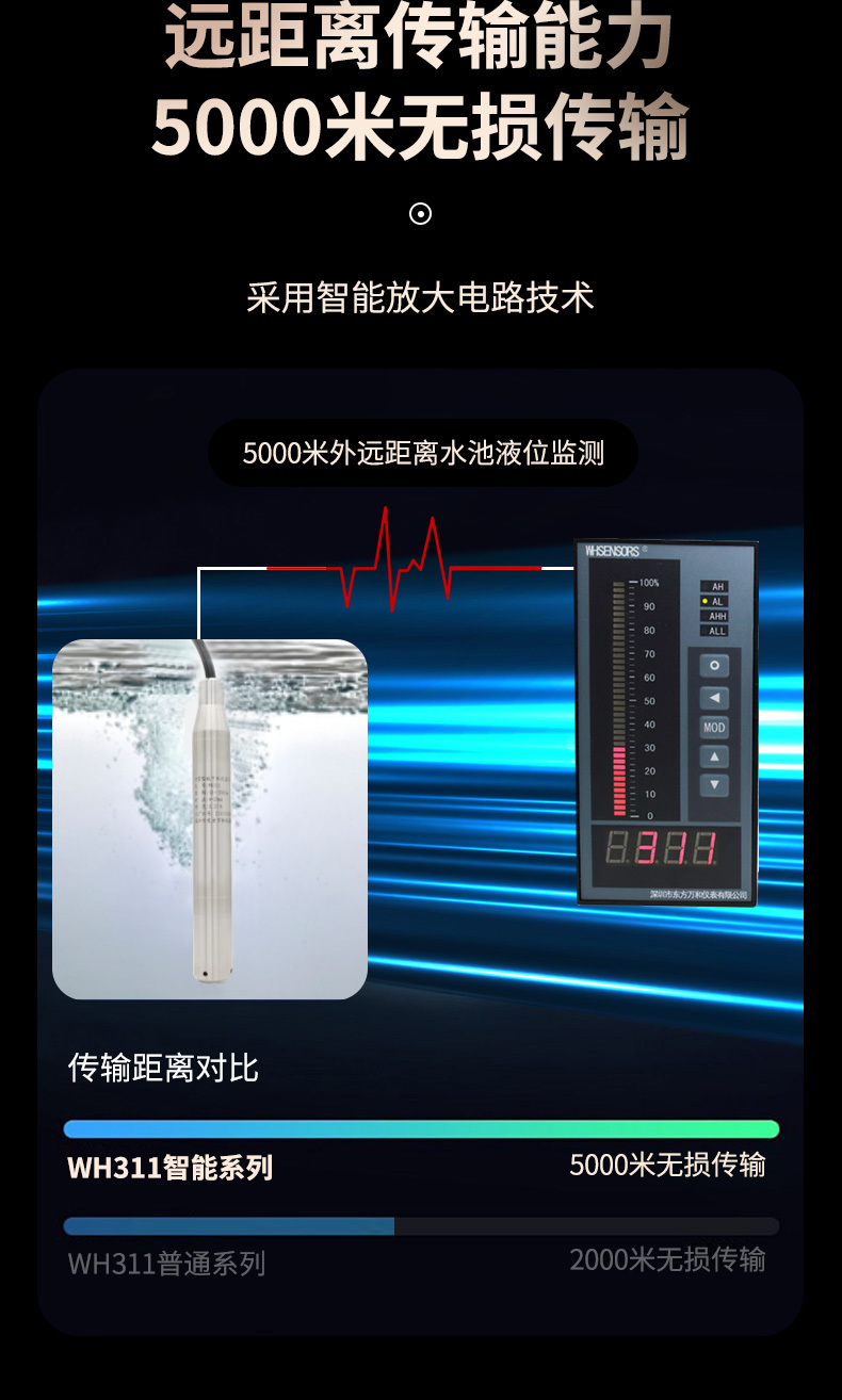
Built-in WHSENSORS Brand sensor chip, signal can be transmitted up to 5000 meters
Output signal: 4-20mA
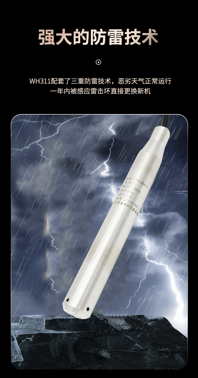
Protection level: IP68
Temperature compensation: -20-85℃
Accuracy: 0.1%FS, 0.25%FS, 0.5%FS
Certification Information:
1 CE FCC RoHS
2 Fire safety third-party inspection report
3 This product has been tested by SGS and the error is 0.009mA
Suitable for remote transmission of water level in fire water tanks and pools
Built-in WHSENSORS Brand sensor chip, signal can be transmitted up to 5000 meters
Classification:
Level Measurement
Keyword:
Water tank level display devices
- Overview
- Overview
- Specs
- Certs
- Applications
-


-
-
-
-
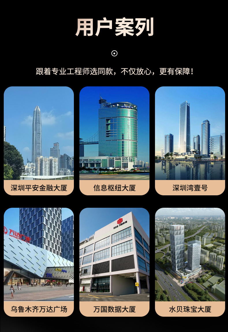
Case Description
I. Typical User Specific Needs
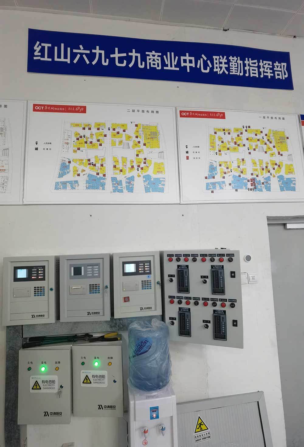
User: Hongshan 6979 Commercial Center

Needs: Hongshan 6979 Commercial Center is one of the landmark buildings in Longhua, Shenzhen.
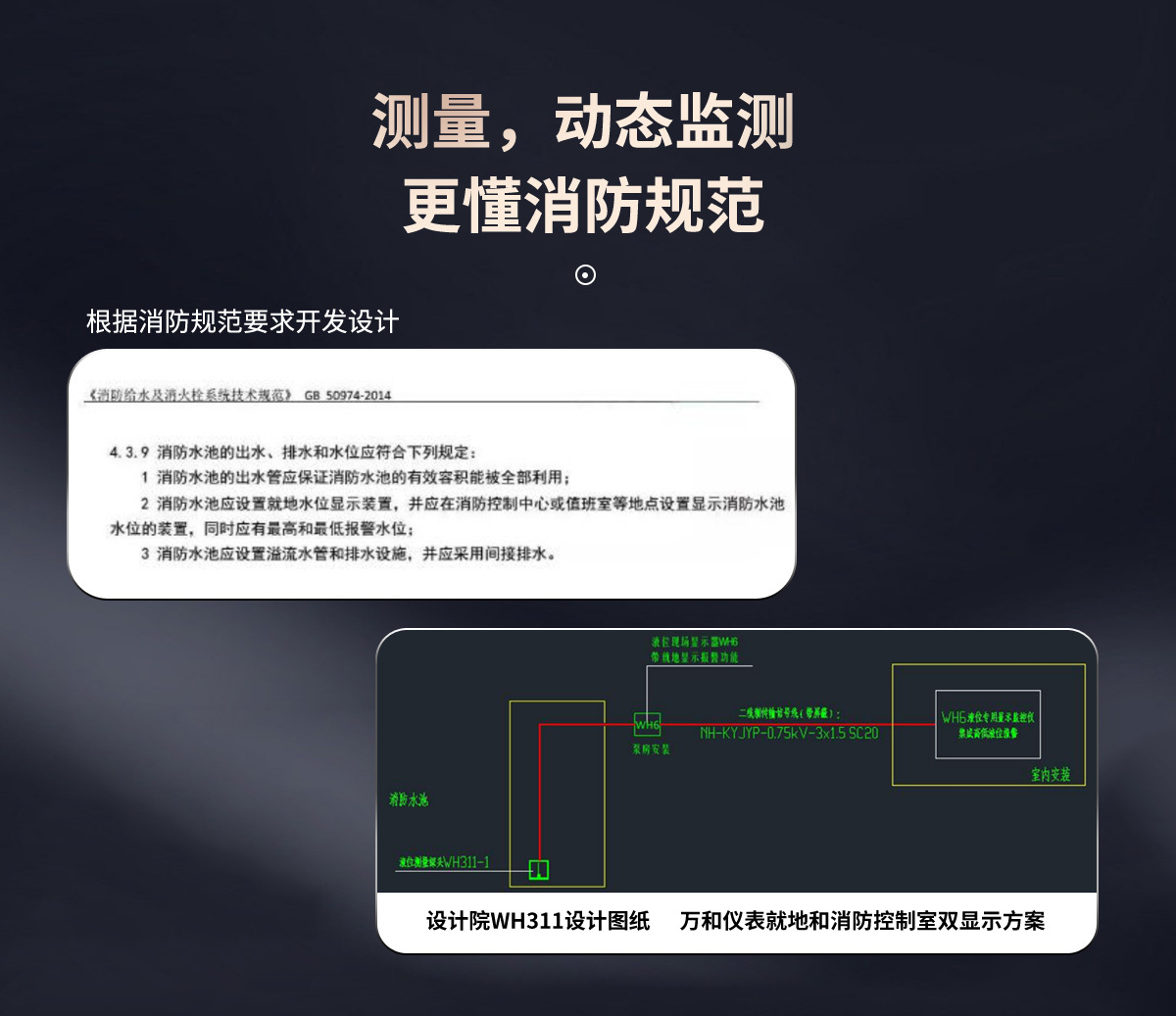
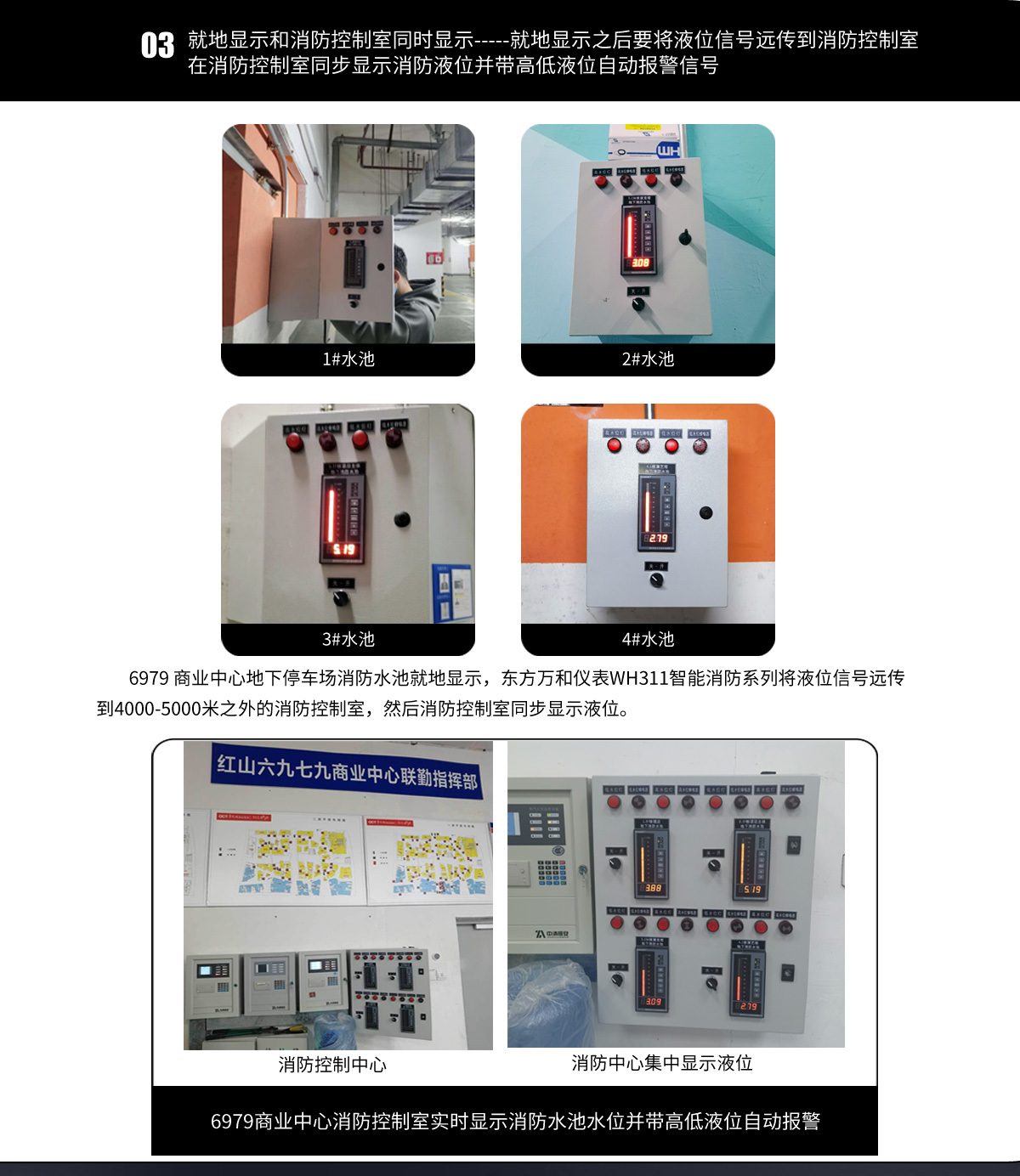
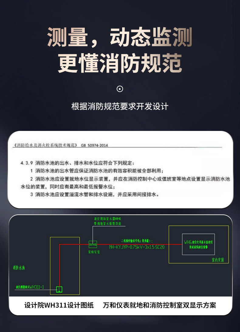
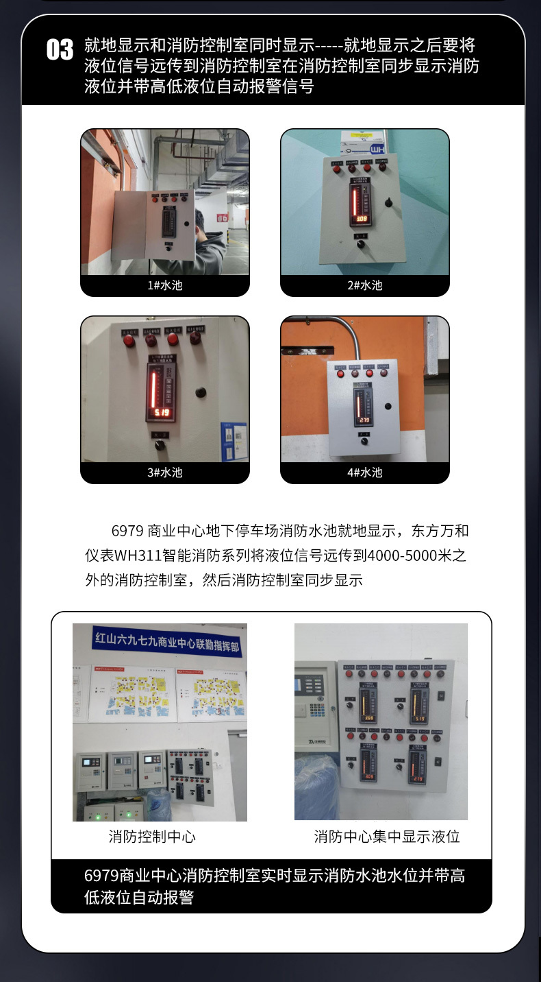
The Hongshan 6979 Commercial Center has four fire water pools, distributed around the underground parking lot, with a water depth of 6 meters and a distance of approximately 3000-4000 meters from the fire control room. The user now requires that according to the fire construction code requirements “GB 50974-2014 4.3.9 clause” (see Figure 1) --Fire water pools should be equipped with on-site water level display devices, and devices displaying the water level of fire water pools should be installed in the fire control center or duty room, etc., and there should be high and low alarm water levels.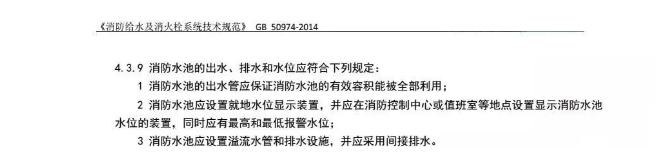
Figure 1
II. Schematic Diagram
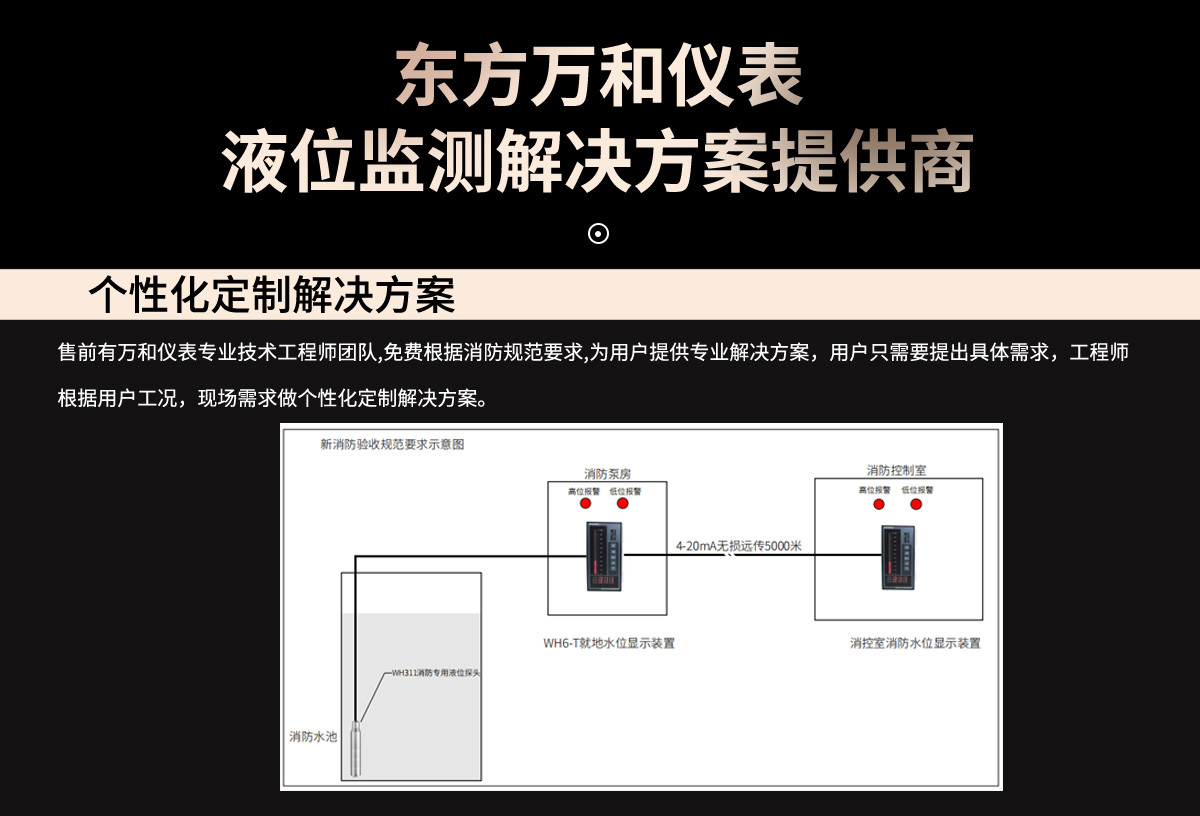
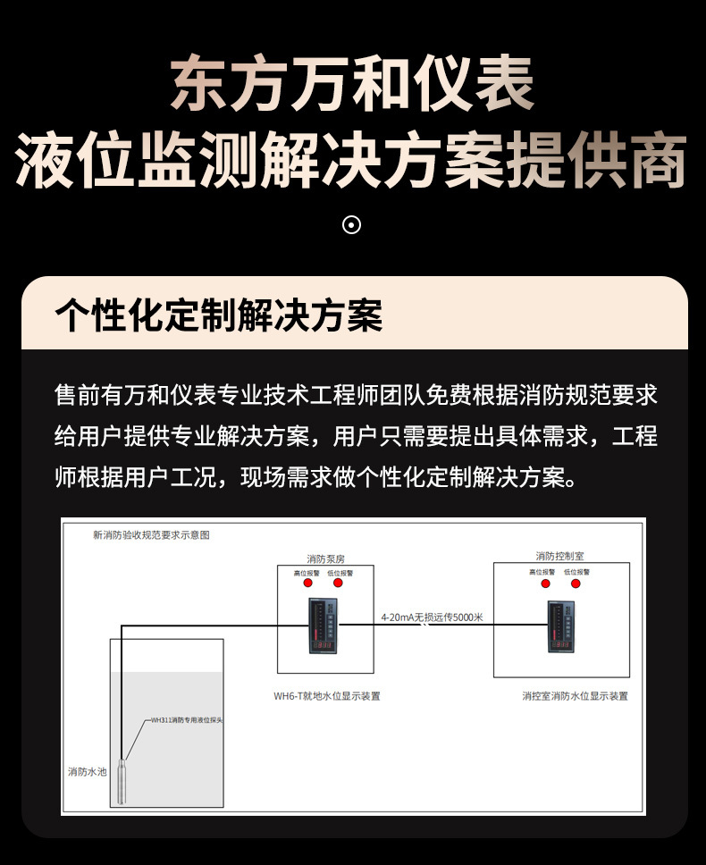
Design and development of a fire water pool level on-site display device and a dual display solution for the fire control room that meets the requirements of the new fire code:
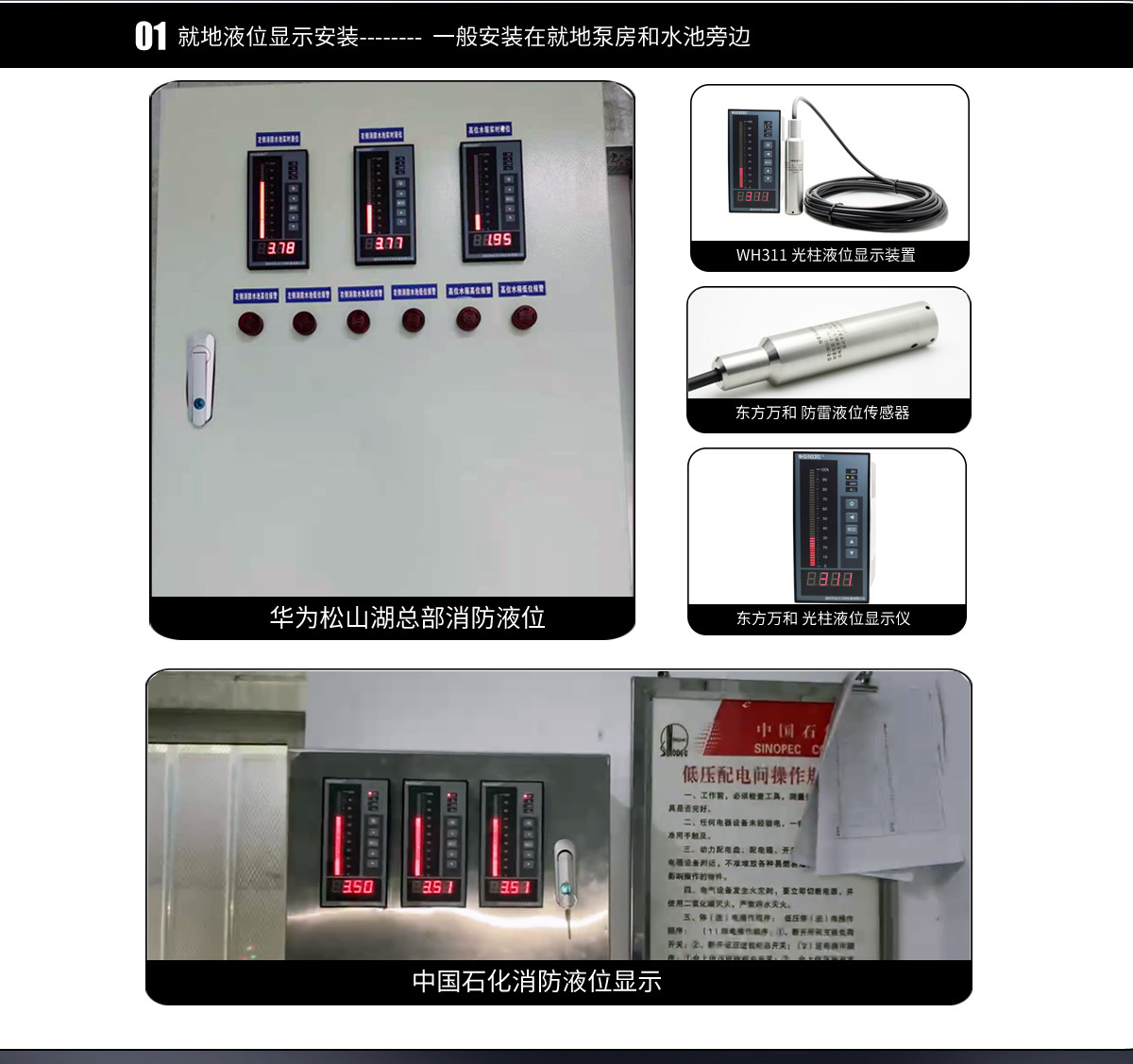
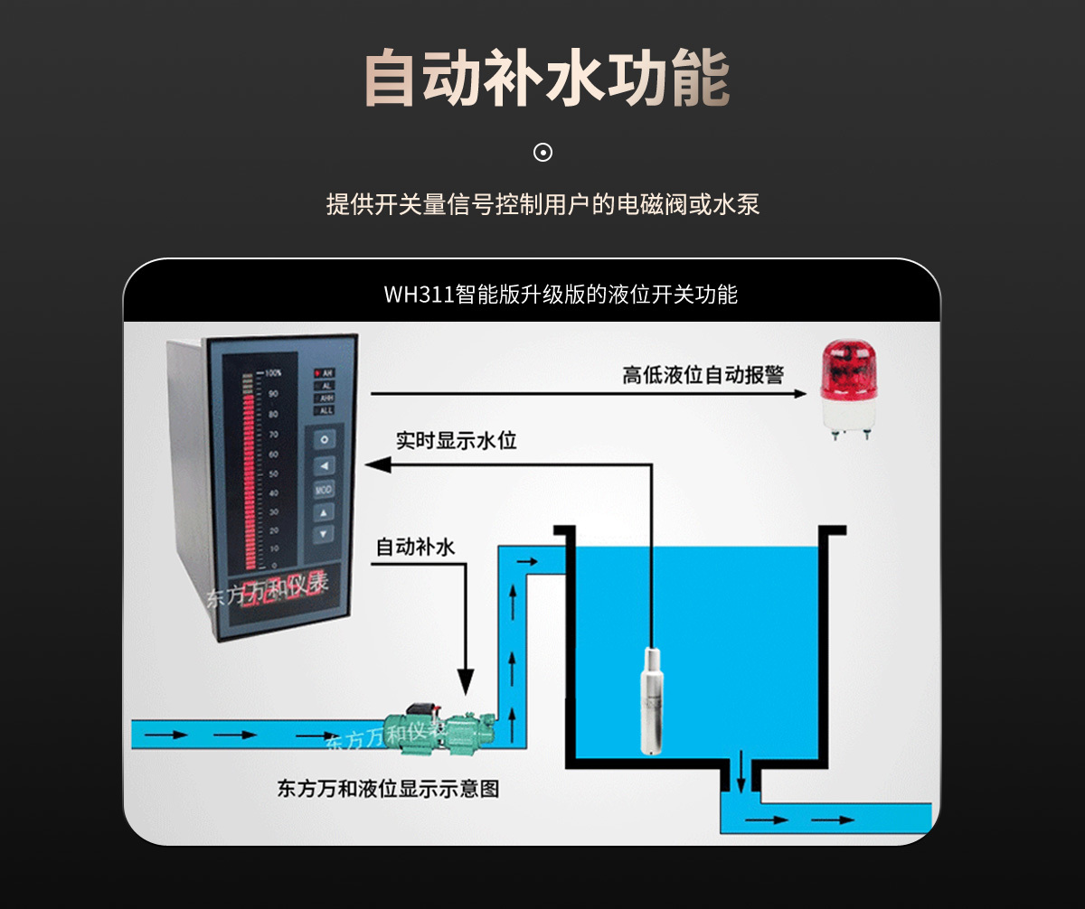
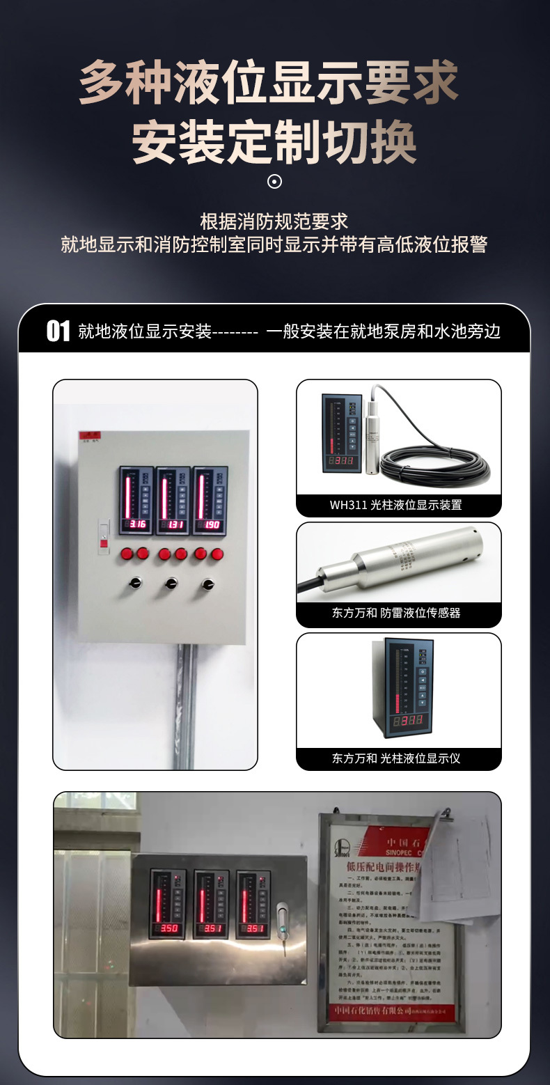
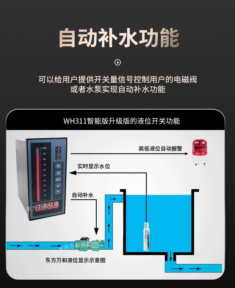
1. Use one level sensor probe with two level displays, one displayed on-site in the user's pump room;
2. Install a 4-20mA remote transmission module (signal transmission up to 5000 meters) on the pump room display WH6-T;
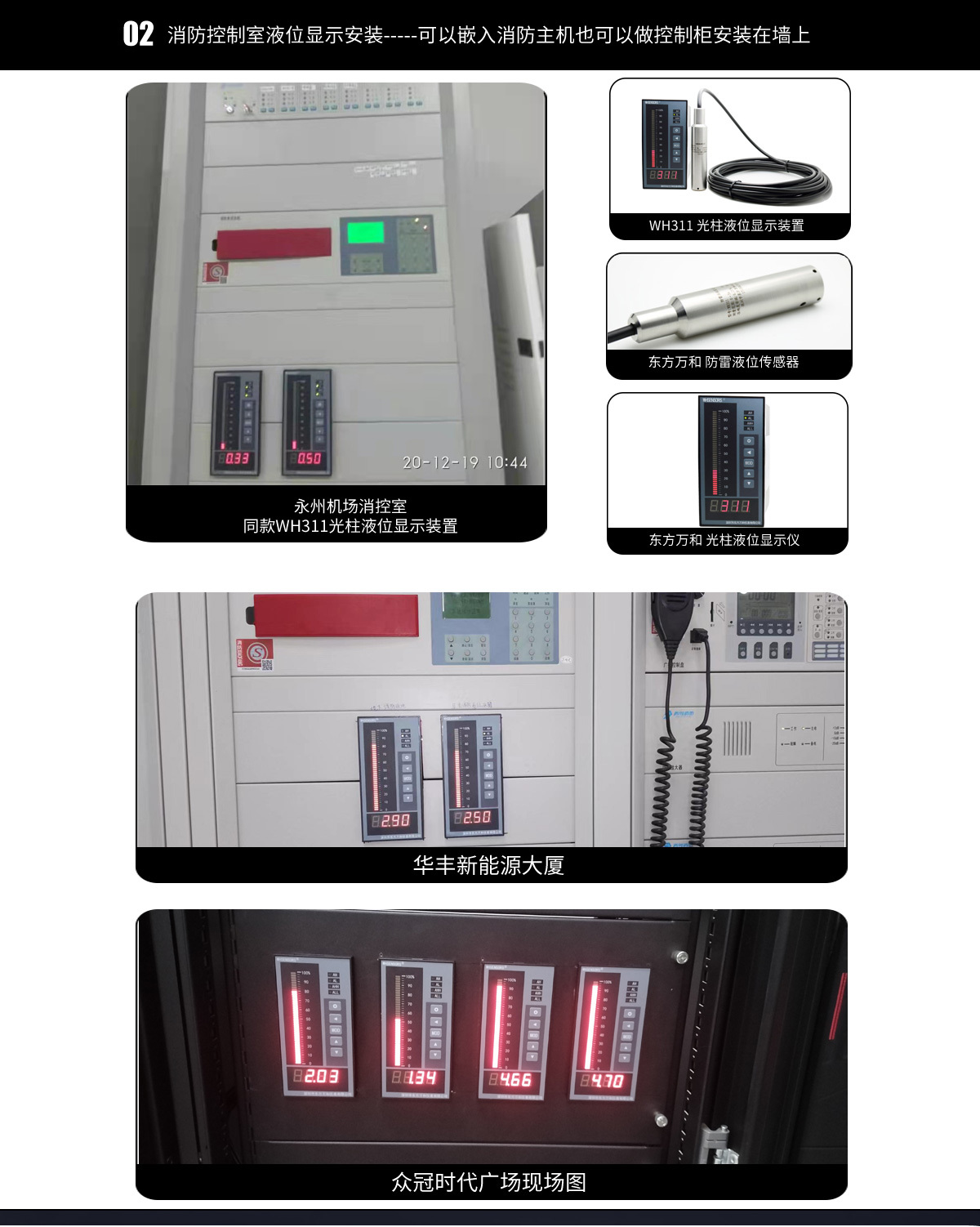
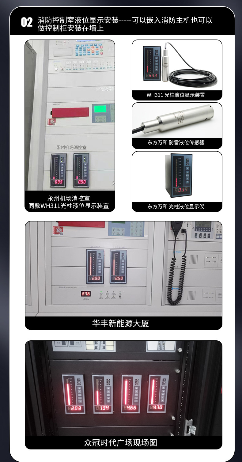
3. Transmit the level signal to the WH6-T light column intelligent level display in the fire control room 4000 meters away for display, with high and low level alarms. This completes our “one-to-two” display.
The following one-to-two display design institute drawing is for reference.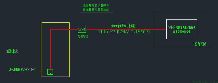
Figure 2 Design Institute Drawings
III. Specific Wiring Scheme Description
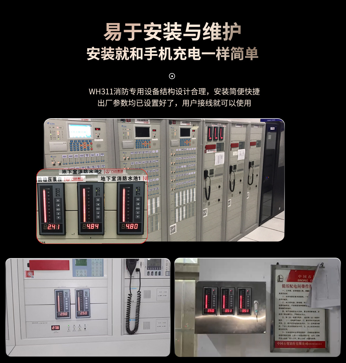
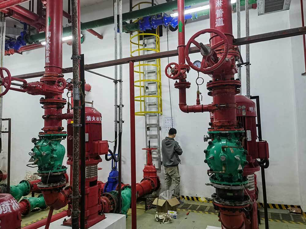
1. Put the WH311 fire-proof lightning protection level sensor probe directly into the bottom of the fire water pool;
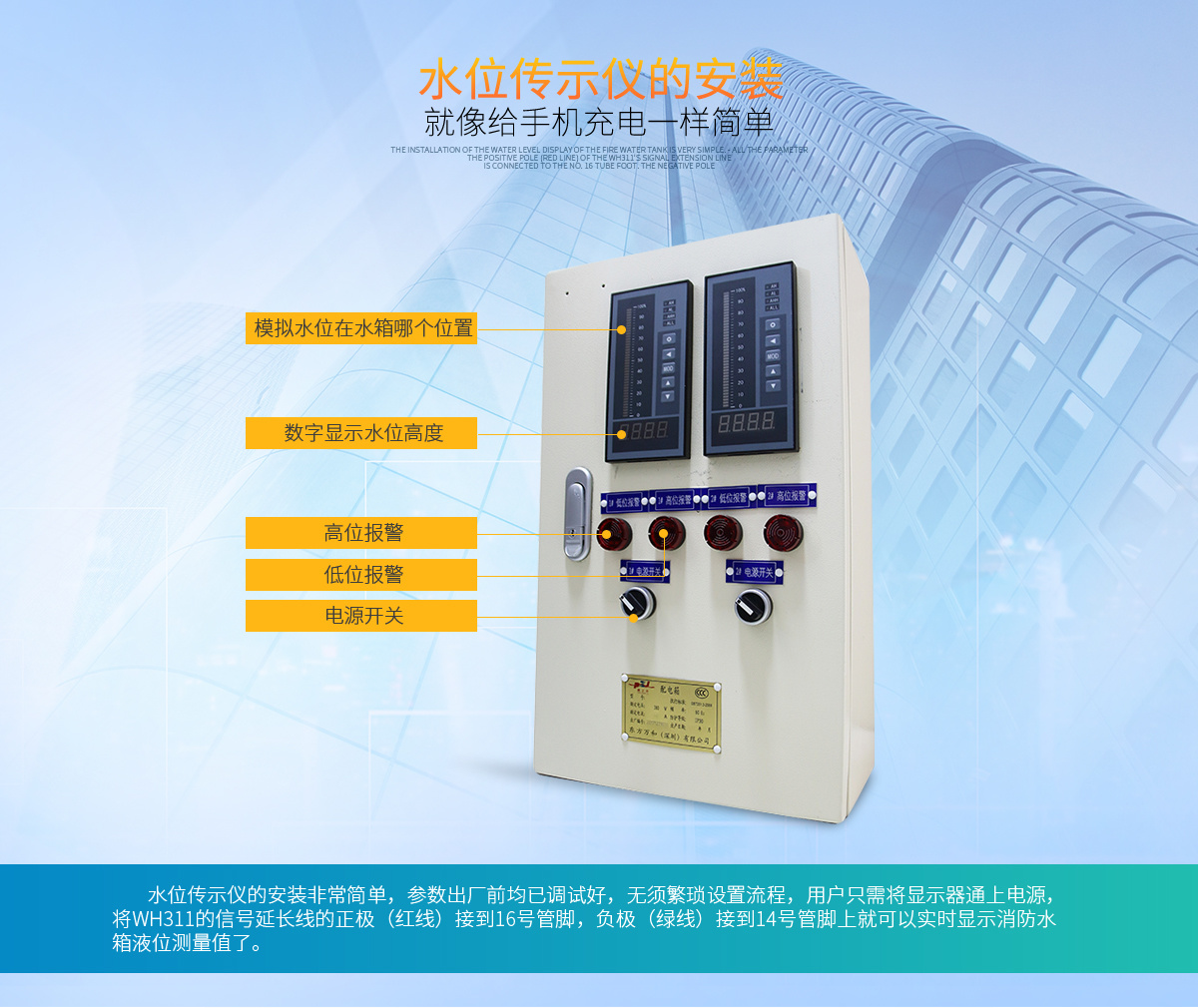
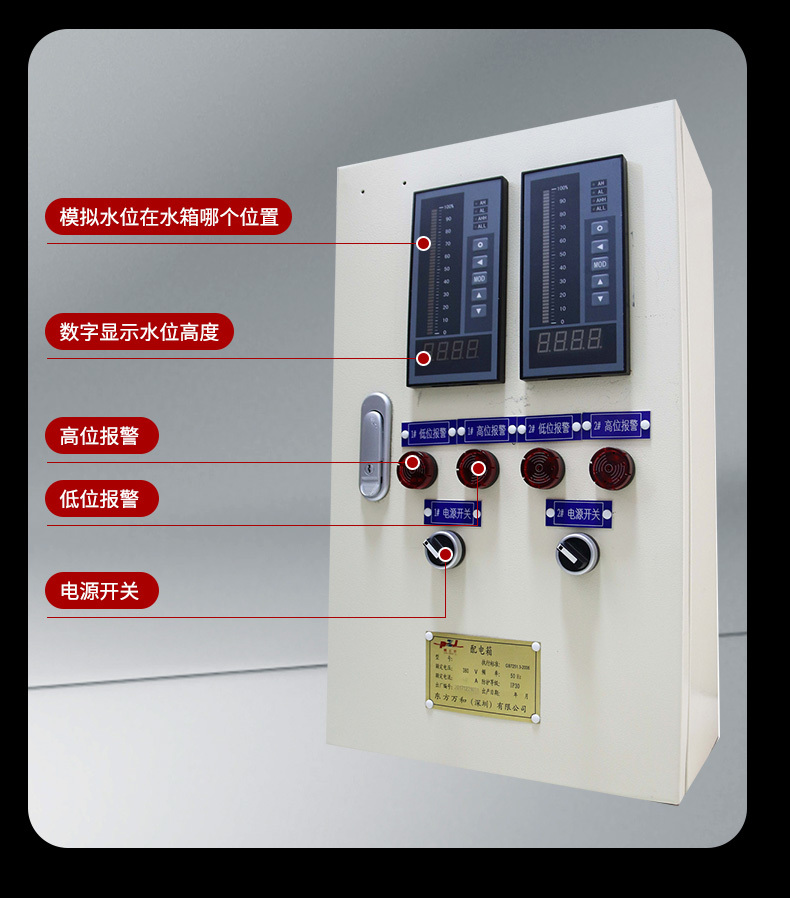
2. Connect the level probe signal line to the WH6-T on-site level display in the pump room via a 2*1.5 square RVVP cable, the red line to terminal 4, and the green line to terminal 1. Short-circuit terminals 2 and 3 with a jumper wire. Terminals 23 and 24 of WH6-T provide a 220V power supply. The WH6-T's built-in 24V power supply module will automatically supply power to the probe WH311. After the wiring is completed, the display screen will display the current fire water level in real time; the user sets the AH high-level alarm value and the AL low-level alarm value according to the requirements.
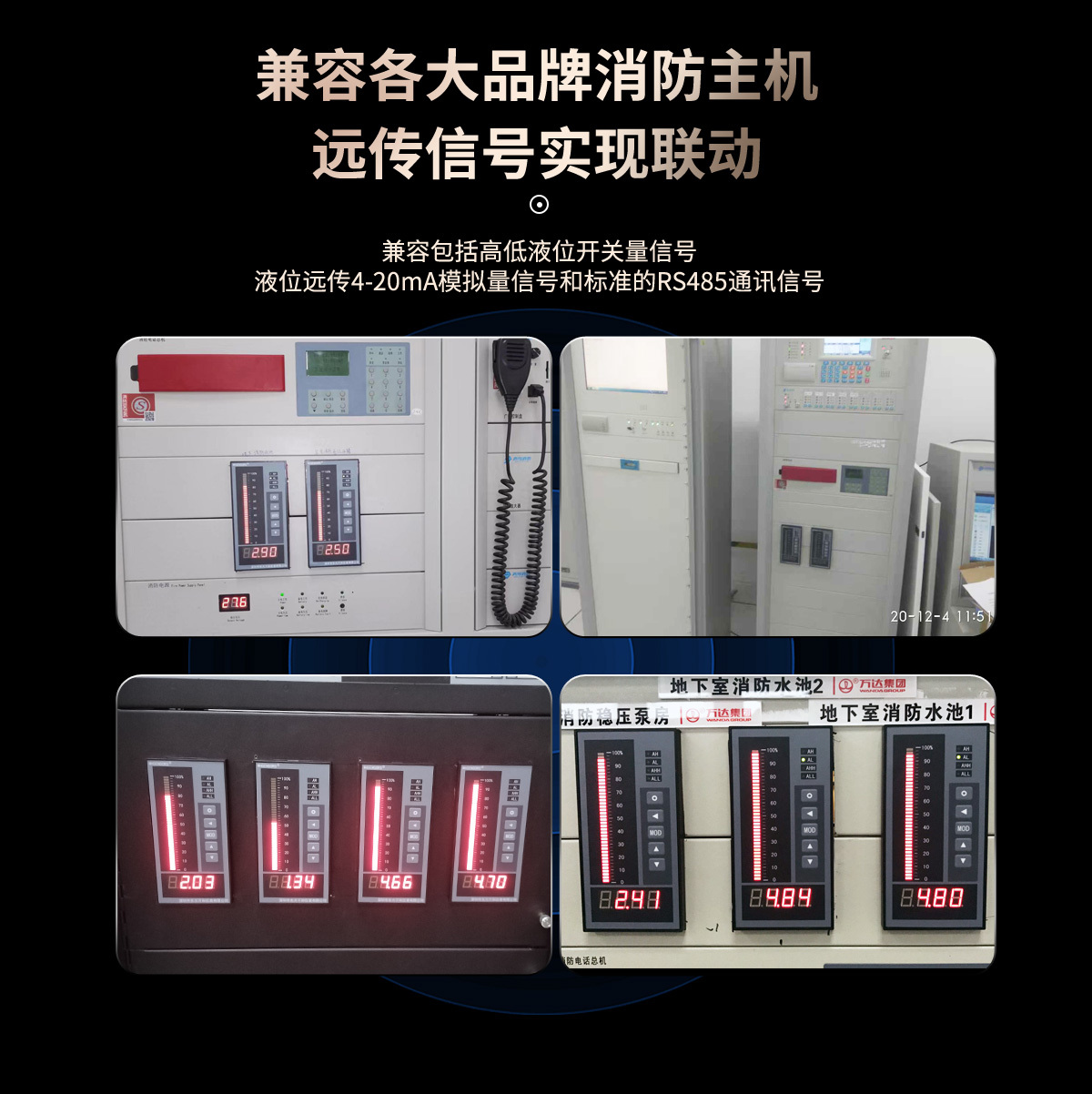
3. Transmit the 4-20mA signal of the pump room display WH6-T output module to the fire control room via a 2*1.5 square RVVP cable. Another WH6-T fire-proof display is installed in the fire control center. Connect the signals of terminals 5 and 6 of the on-site level display output module to terminals 1 and 2 of the fire control room WH6-T display instrument, so that the display instrument in the fire control room will also synchronously display the actual water level of the fire water pool in real time, with percentage intelligent light column display.
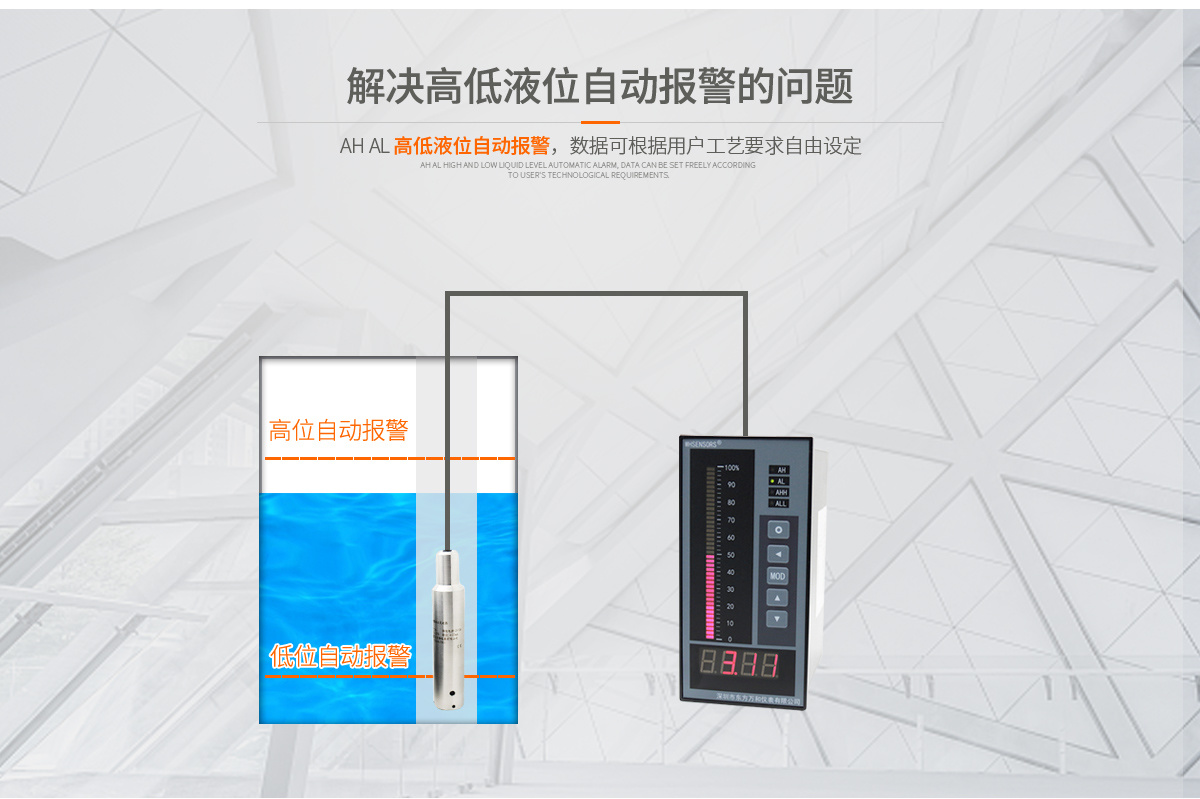
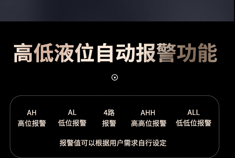
4. Set the high and low level alarm values. When AL is set to 0.5 meters (this value can be set by yourself), the relay operates, the alarm (needs to be provided by the user) is connected, and an audible and visual alarm is issued, thus realizing the low water level alarm function. When AH is set to 4.5 meters (this value can be set by yourself), the relay operates, realizing the high water level alarm.
This realizes the user's requirement to display the fire water pool water level in two places, with automatic high and low level alarm functions. The detailed wiring diagram is as follows.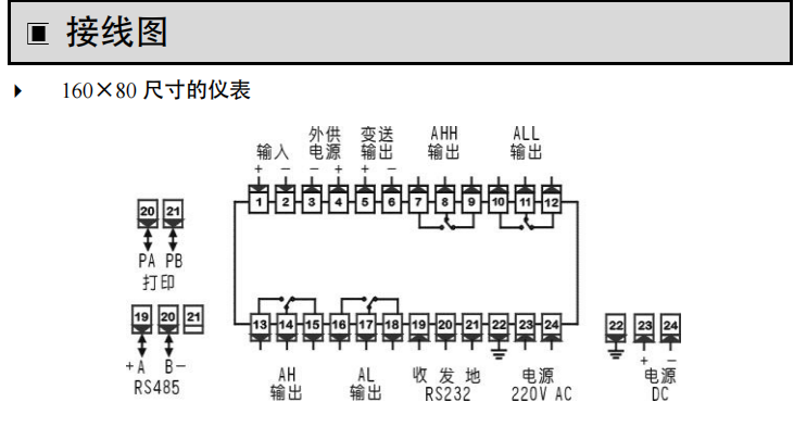
Figure 3 Wiring Diagram
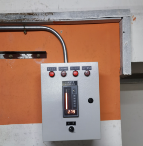
IV. User Adoption Plan, Wanhe Instrument Construction Site Diagram
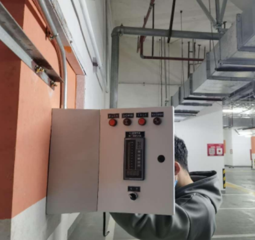
Pool 2
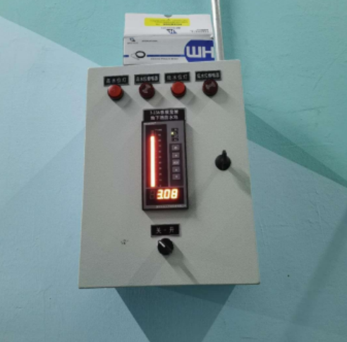
Pool 3
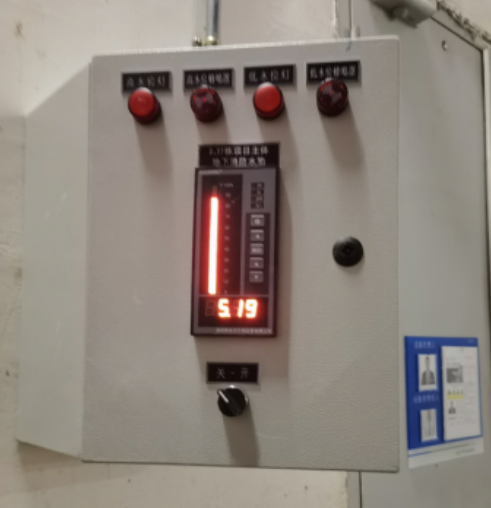
Pool 4
On-site video
Previous Page:
Next page:


Leave us a message
Please leave the content you want to inquire


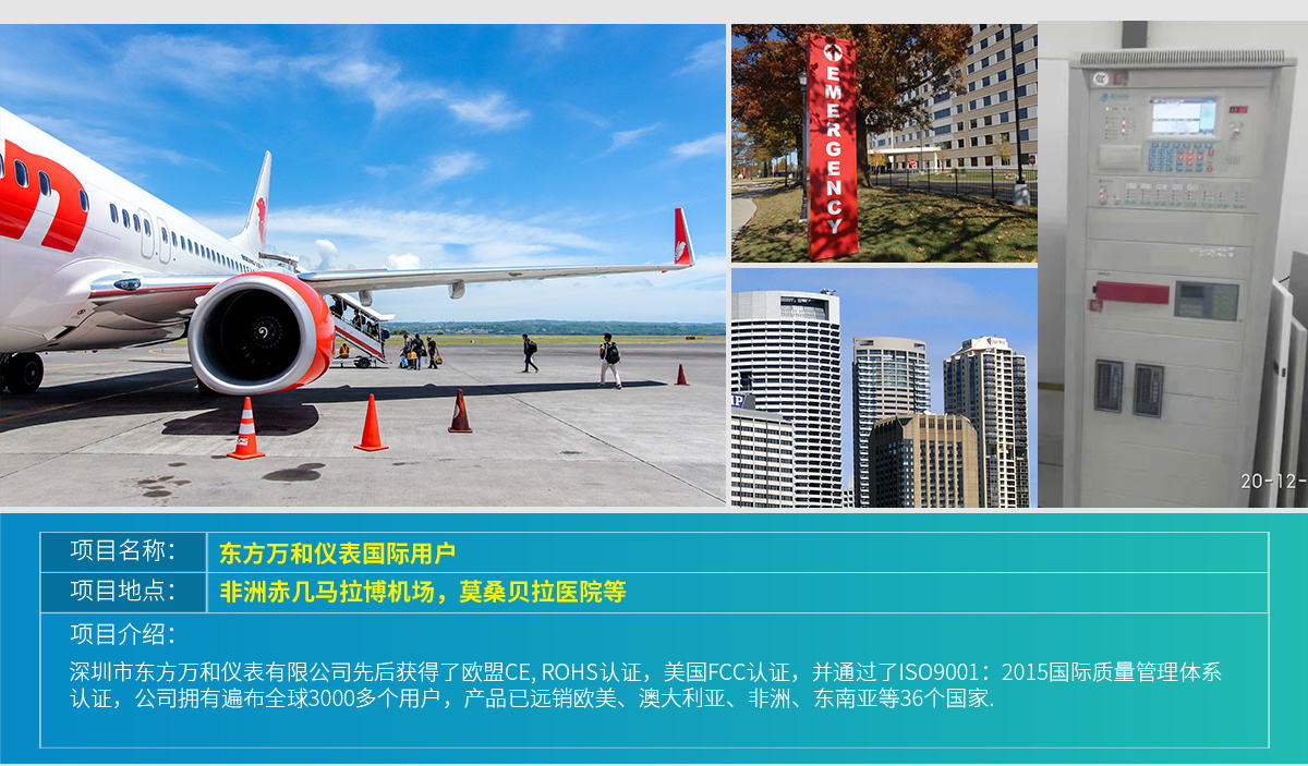
Shenzhen Dongfang Wanhe Instrument Co., Ltd.
Hotline:
4006-033-013
E-mail: dongfangyibiao@163.com
Address: 6th Floor, Tairan 213 Industrial Factory Building, Chegongmiao Industrial Zone, Futian District, Shenzhen